Arduino MKR WIFI 1010
The Arduino MKR WiFi 1010 is the easiest point of entry to basic IoT and pico-network application design. Whether you are looking at building a sensor network connected to your office or home router, or if you want to create a BLE device sending data to a cellphone, the MKR WiFi 1010 is your one-stop-solution for many of the basic IoT application scenarios.
See what Massimo Banzi, Arduino Co-founder, has to say about this board in the following video.
The board's main processor is a low power Arm® Cortex®-M0 32-bit SAMD21, like in the other boards within the Arduino MKR family. The WiFi and Bluetooth® connectivity is performed with a module from u-blox, the NINA-W10, a low power chipset operating in the 2.4GHz range. On top of those, secure communication is ensured through the Microchip® ECC508 crypto chip. Besides that, you can find a battery charger, and a directionable RGB LED on-board.
WiFi and Arduino IoT Cloud
At Arduino we have made connecting to a WiFi network as easy as getting an LED to blink. You can get your board to connect to any kind of existing WiFi network, or use it to create your own Arduino Access Point. The specific set of examples we provide for the MKR WiFi 1010 can be consulted at the WiFiNINA library reference page.
It is also possible to connect your board to different Cloud services, Arduino's own among others. Here some examples on how to get the MKR WiFi 1010 to connect to:
- Arduino's own IoT Cloud: Arduino's IoT Cloud is a simple and fast way to ensure secure communication for all of your connected Things.
- Blynk: a simple project from our community connecting to Blynk to operate your board from a phone with little code
- IFTTT: see an in-depth case of building a smart plug connected to IFTTT
- AWS IoT Core: we made this example on how to connect to Amazon Web Services
- Azure: visit this github repository explaining how to connect a temperature sensor to Azure's Cloud
- Firebase: you want to connect to Google's Firebase, this Arduino library will show you how
Bluetooth® and BLE
The communications chipset on the MKR WiFi 1010 can be both a BLE and Bluetooth® client and host device. Something pretty unique in the world of microcontroller platforms.
The Arduino MKR WiFi 1010 is based on the SAMD21 microcontroller.
| Microcontroller | SAMD21 Cortex®-M0+ 32bit low power ARM MCU (datasheet) |
| Radio module | u-blox NINA-W102 (datasheet) |
| Board Power Supply (USB/VIN) | 5V |
| Secure Element | ATECC508 (datasheet) |
| Supported Battery | Li-Po Single Cell, 3.7V, 1024mAh Minimum |
| Circuit Operating Voltage | 3.3V |
| Digital I/O Pins | 8 |
| PWM Pins | 13 (0 .. 8, 10, 12, 18 / A3, 19 / A4) |
| UART | 1 |
| SPI | 1 |
| I2C | 1 |
| Analog Input Pins | 7 (ADC 8/10/12 bit) |
| Analog Output Pins | 1 (DAC 10 bit) |
| External Interrupts | 8 (0, 1, 4, 5, 6, 7, 8, 16 / A1, 17 / A2) |
| DC Current per I/O Pin | 7 mA |
| CPU Flash Memory | 256 KB (internal) |
| SRAM | 32 KB |
| EEPROM | no |
| Clock Speed | 32.768 kHz (RTC), 48 MHz |
| LED_BUILTIN | 6 |
| USB | Full-Speed USB Device and embedded Host |
| Length | 61.5 mm |
| Width | 25 mm |
| Weight | 32 gr. |
Schematics
The MKR WiFi 1010 is open-source hardware! You can build your own board using the following files:
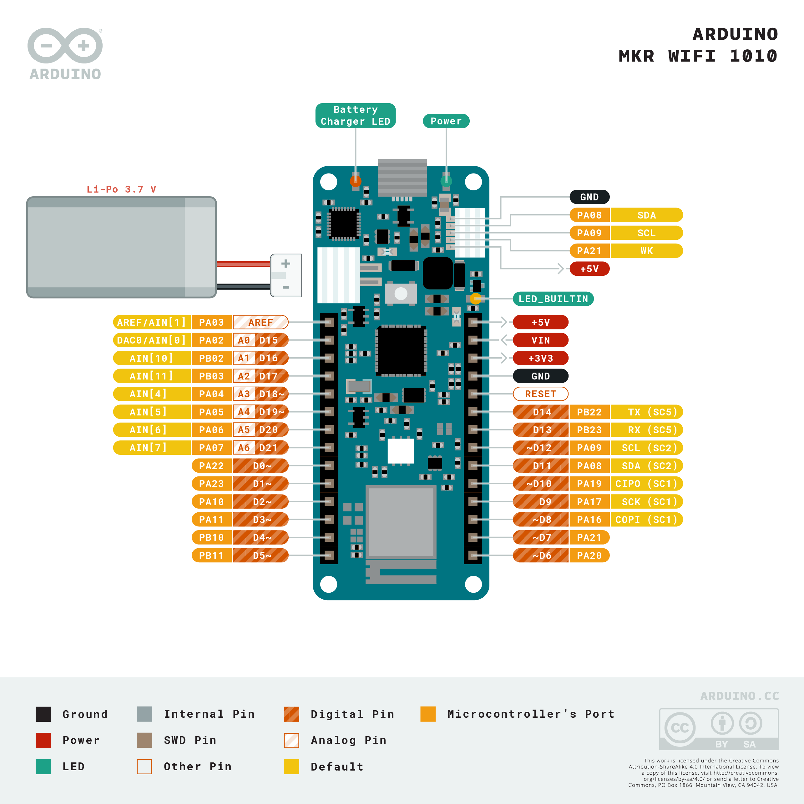
Pinout Diagram

Download the full pinout diagram as PDF here.
Additional I2C Port
The MKR WiFi 1010 has an additional connector meant as an extension of the I2C bus. It's a small form factor 5-pin connector with 1.0 mm pitch. The mechanical details of the connector can be found in the connector's datasheet.
The I2C port, also referred to as the Eslov self-identification port within Arduino, comes with: SDA, SCL, GND, +5V, and an extra digital pin meant to send an alarm to the otherwise plain I2C devices connected to it. The pinout is shown in the following image:

If you are interested in designing your own modules for Arduino boards with this expansion port, the connector we suggest using is code: SHR-05V-S-B, also in the picture.
Enter the code in the box below:


