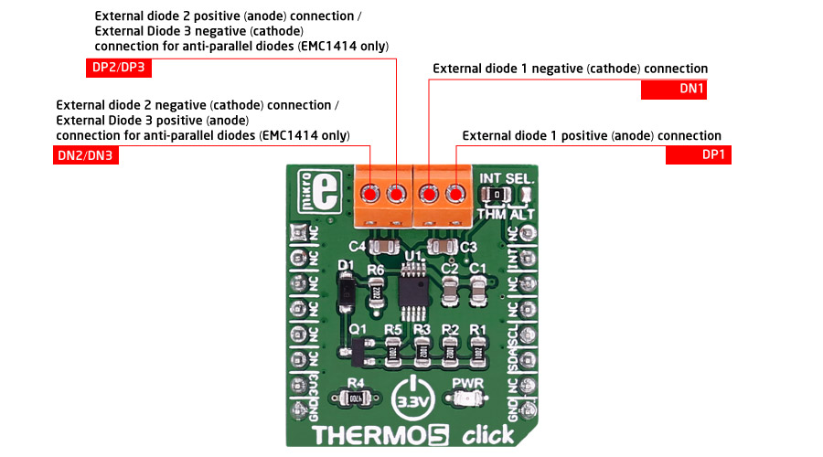
THERMO 5 click
The click can monitor four temperature channels - three external and one internal.

THERMO 5 click features
THERMO 5 click can be used to measure temperatures with up to two/three externally connected diodes.
Each external diode channel is configured with Resistance Error Correction and Beta Compensation based on user settings and system requirements.
The device contains programmable High, Low, and Thermo limits for all measured temperature channels.
If the measured temperature goes below the Low limit or above the High limit, the ALERT pin can be asserted (based on user settings).
If the measured temperature meets or exceeds the Thermo Limit, the THERM pin is asserted unconditionally, providing two tiers of temperature detection.
EMC1414 features
The EMC1414 monitors four temperature channels. It provides ±1°C accuracy for both external and internal diode temperatures.
Resistance Error Correction feature automatically eliminates the temperature error caused by series resistance allowing greater flexibility in routing thermal diodes.
Beta Compensation feature eliminates temperature errors caused by low, variable beta transistors common in today’s fine geometry processors.
Specifications
| Type | Temperature,Humidity |
| Applications | Personal computers, electronics equipment, industrial controllers |
| On-board modules | EMC1414 temperature sensor |
| Key Features | ±1°C accuracy, 0.125°C resolution |
| Interface | I2C,GPIO |
| Input Voltage | 3.3V or 5V |
| Compatibility | mikroBUS |
| Click board size | S (28.6 x 25.4 mm) |
Pinout diagram
This table shows how the pinout on THERMO 5 click corresponds to the pinout on the mikroBUS™ socket (the latter shown in the two middle columns).
Programming
Code examples for THERMO 5 click, written for MikroElektronika hardware and compilers are available on Libstock.
Code snippet
This code snippet initializes the MCU, the TFT display and I2C module. In an infinite loop we are reading 4 different temperatures from diodes and displaying them on screen.
01 //Main program
02   void main()
03   {
04    // MCU Init
05    AD1PCFG = 0xFFFF;            // Configure AN pins as digital I/O
06    JTAGEN_bit = 0;              // Disable JTAG
07    TRISA  = 0;                  // Configure PORTA as output
08    TRISB  = 0;                  // Configure PORTB as output
09    TRISC  = 0;                  // Configure PORTC as output
10    TRISD  = 0;                  // Configure PORTD as output
11
12    LATA = 0;                    //Set PORTA value to zero
13    LATB = 0;                    //Set PORTB value to zero
14    LATC = 0;                    //Set PORTC value to zero
15    LATD = 0;                    //Set PORTD value to zero
16
17    // TFT Init
18    TFT_BLED_Direction = 0;
19    TFT_Init_ILI9341_8bit(320, 240);
20    TFT_BLED = 1;
21    DrawFrame();
22
23    // I2C Init
24    I2C2_Init_Advanced(50000, 100000);
25    delay_ms(500);
26    // Sets the I2C1 module active
27    I2C_Set_Active(&I2C2_Start,
28                   &I2C2_Restart,
29                   &I2C2_Read,
30                   &I2C2_Write,
31                   &I2C2_Stop,
32                   &I2C2_Is_Idle);
33
34    diodeTemperature = 0.0;
35
36
37    // Temperature read loop
38    while (1)
39    {
40       TFT_Rectangle( 200, 50, 280, 200 );
41
42       diodeTemperature = TH5Read(INT_DIODE);
43       sprintf( txt, "%.2f C", diodeTemperature);
44       TFT_Write_Text( txt, 200, 60 );
45
46       diodeTemperature = TH5Read(EXT_DIODE1);
47       sprintf( txt, "%.2f C", diodeTemperature);
48       TFT_Write_Text( txt, 200, 100 );
49
50       diodeTemperature = TH5Read(EXT_DIODE2);
51       sprintf( txt, "%.2f C", diodeTemperature);
52       TFT_Write_Text( txt, 200, 140 );
53
54       diodeTemperature = TH5Read(EXT_DIODE3);
55       sprintf( txt, "%.2f C", diodeTemperature);
56       TFT_Write_Text( txt, 200, 180 );
57
58       delay_ms(500);
59    }
Downloads
mikroBUS™ Standard specificationEnter the code in the box below:


