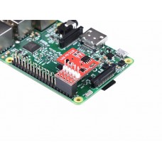
Raspberry Pi RTC Expansion Module v1.1
The RTC module is specifically designed for Raspberry Pi. It communicated with Raspberry Pi through I2C bus. There is a Maxim DS1307 and CR1220 button cell on the board to keep the real time for a long time after the Raspberry Pi has it’s power off. In order to offering a convenient way to debug, there are five pin has been setup which are 5v, 3.3v, Rxd,Txd on borad.
Features
-
Use Maxim DS1307 chip
-
Extends CR1220 button cell backup
-
Can be operated by a shell
-
Set a serial port connector
-
Programmable square-wave output signal
-
Consumes Less than 500nA in Battery-Backup Mode
-
Automatic Power-Fail Detect and Switch Circuitry
-
Programmable Square-Wave Output Signal
Parameters
-
Accuracy ±2ppm from 0°C to +40°C
-
Work voltage 5V
-
Battery Backup Input for Continuous Time keeping
-
Real-Time Clock Counts Seconds, Minutes, Hours, Day, Date, Month, and Year with Leap Year • Compensation Valid Up to 2100
-
Work temperature 0°C to +70°C
Documents
It will be appreciated if you can help us improve the documents, add more demo code or tutorials. For technical support, please post your questions to our forum.
Technical Details
| Battery | Exclude |
Part List
| Raspberry Pi RTC Expansion Module v1.1 | 1 |
Enter the code in the box below:

-74x74.jpg)


