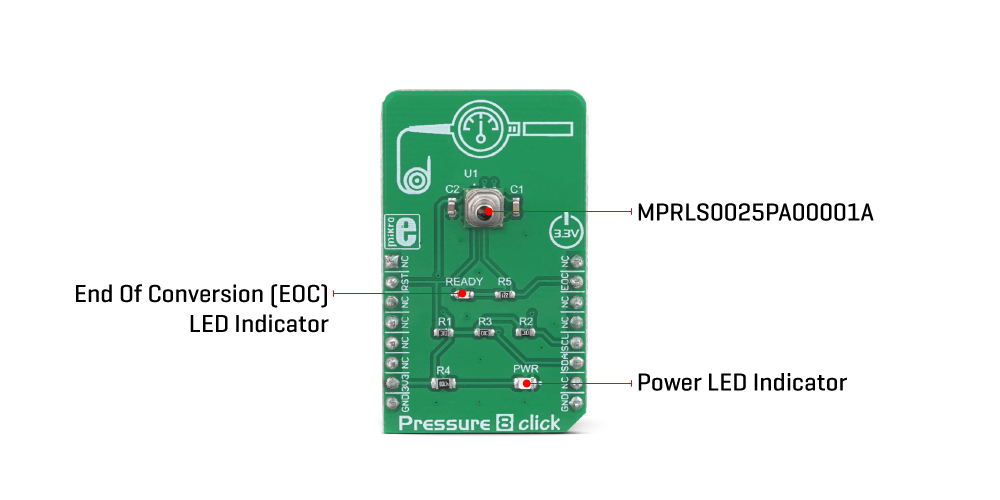
Pressure 8 Click
MPR series sensors offer many benefits, making them ideally suited to be used on many different application designs. By featuring the MPRLS0025PA00001A absolute pressure sensor, Pressure 8 click is the perfect tool for development of pressure-based applications, including humidifiers, air beds, washing and dish machines, airflow monitors, and similar applications based on the accurate pressure measurement and monitoring.
How does it work?
Pressure 8 click features the MPRLS0025PA00001A, an accurate compensated absolute pressure sensor, by Honeywell. This sensor offers a range of highly useful features. The most distinctive feature of this sensor is its high accuracy and ability to output compensated 24-bit values over the I2C interface. This MPR series sensor integrates an ASIC (Application Specific Integrated Circuit), along with the piezoresistive silicon pressure sensor. Thanks to the integrated ASIC, this sensor can output 24-bit compensated measurements within the range of 0 psi to 25 psi (0 to about 172kPa), and temperatures from 0 °C to 50 °C. Due to the silicone gel protection, it can be used with a variety of liquid media.

The casing of the MPRLS0025PA00001A sensor is built of stainless steel, preventing the rust formation. All the electronic components within the sensor are protected by a silicone gel, allowing the sensor to be used with a wide variety of liquid media. It can be used to mesure absolute pressure values up to 25 psi, or about 172 kPa. However, the sensor can be exposed up to 60 psi (about 414 kPa) of overpressure, without causing permanent damage. The absolute maximum pressure allowed is 120 psi (about 825 kPa). Exposing the sensor to absolute maximum pressure will damage it permanently, and it will not be functional anymore. Pressure beyond this point will physically destroy the sensor, resulting in possible leakage.
There is a range of errors common to any sensor of this type, that affect its accuracy. The term "Total Error Band" (TEB) is used within the datasheet of the MPRLS0025PA00001A sensor to better illustrate its accuracy, considering all of the pressure measurement errors, combining them into a single parameter. The datasheet specifies the TBD of the sensor to be ±1.5. It also offers a transfer function, which can e used to calculate the output pressure value based on a 24-bit result, provided over the I2C interface.
The first byte after the conversion command is sent over the I2C interface is the content of the status register. It contains a BUSY flag (bit 5) among other status bits. It indicates the end of conversion, so the software should poll the status byte and wait this bit to be reset. Another, much simpler method is to use the EOC (End of Conversion) pin, routed to the mikroBUS™ INT pin, labeled as EOC on this Click Board™. This pin allows much simpler software routine to be written, using the EOC pin to trigger an interrupt on the host microcontroller (MCU). A HIGH logic level on this pin indicates that the conversion is finished. Lastly, the user can simply wait at least 5ms for the conversion to complete, before issuing another command.
The RES pin of the sensor is used to perform a hardware reset. This pin is routed to the mikroBUS™ RST pin, and a logic LOW pulse on this pin will reset the sensor IC. It is pulled to a HIGH logic level by an onboard resistor preventing it to float and uncontrollably reset the sensor, if the corresponding pin is tri-stated on the host MCU.
The EOC event is also signaled visually, by a LED labeled as READY. This LED provides visual feedback about the status of the conversion: when lit, it indicates that the conversion is ended, and the measurement conversion data can be retrieved over the I2C interface.
Pressure 8 click is supported by the mikroSDK compatible library of functions that encapsulate all the necessary conversions and status checking, returning the measured value converted into physical units, directly. This vastly simplifies and speeds up the development process.
This Click Board™ uses the I2C communication interface. It has pull-up resistors connected to the mikroBUS™ 3.3V rail. Proper conversion of logic voltage levels should be applied before the Click board™ is used with MCUs operated with 5V.
Specifications
| Type | Pressure / Altitude |
| Applications | Pressure 8 click is the perfect tool for development of pressure-based applications, including humidifiers, air beds, washing and dish machines, airflow monitors, and similar applications based on the accurate pressure measurement and monitoring. |
| On-board modules | MPRLS0025PA00001A, an accurate compensated absolute pressure sensor, by Honeywell. |
| Key Features | Built in ASIC for output data processing, 24-bit conversion, low count of external components required, stainless-steel water-proof casing offers reliability and long-term stability, etc. |
| Interface | I2C |
| Input Voltage | 3.3V |
Pinout diagram
This table shows how the pinout on Pressure 8 Click corresponds to the pinout on the mikroBUS™ socket (the latter shown in the two middle columns).
Onboard settings and indicators
| Label | Name | Default | Description |
|---|---|---|---|
| LD1 | PWR | - | Power LED indicator |
| LD2 | READY | - | End of Conversion (EOC) LED Indicator |
Pressure 8 click electrical specifications
| Description | Min | Typ | Max | Unit |
|---|---|---|---|---|
| Pressure range | 0 | - | 25 | psi |
| Compensated temperature range | 0 | - | +50 | ˚C |
| Operating temperature range | -40 | - | +85 | ˚C |
| Data rate | - | 200 | - | Samples/s |
Software support
We provide a library for the Pressure 8 Click on our LibStock page, as well as a demo application (example), developed using MikroElektronika compilers. The demo can run on all the main MikroElektronika development boards.
Library Description
The library initializes and defines the I2C bus driver and drivers that offer a choice for writing data in register and reads data form register. The library includes function for read Pressure data in mBar/hPa/kPa/Torr or mmHg. The user also has the function for set PSI Range, function for reset device, function for get read Satatus and function for read interrupt state.
Key functions:
float pressure8_getPressure(uint8_t pressureIn)- Functions for get Pressure data.void pressure8_reset()- Functions for reset device.void pressure8_setPSIRange(float PSI_min, float PSI_max)- Functions for set PSI range.
Examples description
The application is composed of the three sections :
- System Initialization - Initializes I2C module and sets INT pin as INPUT and RST pin as OUTPUT.
- Application Initialization - Initialization driver init, reset device and set PSI range.
- Application Task - (code snippet) - Reads Pressure data and this data logs to USBUART every 1 sec.
void applicationTask()
{
    float PressureData;
    char demoText[ 50 ];

    PressureData = pressure8_getPressure(_PRESSURE8_DATA_IN_mBar);
    FloatToStr(pressureData, demoText);
    mikrobus_logWrite(" Pressure data : ", _LOG_TEXT);
    mikrobus_logWrite(demoText, _LOG_TEXT);
    mikrobus_logWrite(" mBar", _LOG_LINE);
    Delay_ms( 1000 );
}
The full application code, and ready to use projects can be found on our LibStock page.
Other mikroE Libraries used in the example:
I2C
Additional notes and informations
Depending on the development board you are using, you may need USB UART click, USB UART 2 click or RS232 click to connect to your PC, for development systems with no UART to USB interface available on the board. The terminal available in all MikroElektronika compilers, or any other terminal application of your choice, can be used to read the message.
Downloads
mikroBUS™ Standard specificationEnter the code in the box below:


