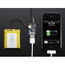
PowerBoost 500 Charger - Rechargeable 5V Lipo USB Boost @ 500mA+
PowerBoost 500C is the perfect power supply for your portable project! With a built-in battery charger circuit, you'll be able to keep your project running even while recharging the battery! This little DC/DC boost converter module can be powered by any 3.7V LiIon/LiPoly battery, and convert the battery output to 5.2V DC for running your 5V projects.
If you need a 1A battery charger, smart load-sharing, and 1A iOS resistors, check out the Powerboost 1000C
Like our popular 5V 1A USB wall adapter, we tweaked the output to be 5.2V instead of a straight-up 5.0V so that there's a little bit of 'headroom' for long cables, high draw, the addition of a diode on the output if you wish, etc. The 5.2V is safe for all 5V-powered electronics like Arduino, Raspberry Pi, or Beagle Bone while preventing icky brown-outs during high current draw because of USB cable resistance.
The PowerBoost 500C has at the heart a TPS61090 boost converter from TI. This boost converter chip has some really nice extras such as low battery detection, 2A internal switch, synchronous conversion, excellent efficiency, and 700KHz high-frequency operation. Check out these specs!
- Synchronous operation means you can disconnect the output completely by connecting the ENable pin to ground. This will completely turn off the output
- 2A internal switch (~2.5A peak limiting) means you can get 500mA+ from a 3.7V LiPoly/LiIon battery. We had no problem drawing 1000mA, just make sure your battery can handle it!
- Low battery indicator LED lights up red when the voltage dips below 3.2V, optimized for LiPo/LiIon battery usage
- Onboard 500mA charge-rate 'iOS' data resistors. Solder in the USB connector and you can plug in any iPhone or iPod for 500mA charge rate. Not suggested for large iPads.
- Full breakout for battery in, control pins and power out
- 90%+ operating efficiency in most cases (see datasheet for efficiency graphs), and low quiescent current: 5mA when enabled and power LED is on, 20uA when disabled (power and low batt LED are off)
To make this even more useful, we stuck a MicroLipo charger on the other side. The charger circuitry is powered from a microUSB jack, and will recharge any 3.7V/4.2V LiIon or LiPoly battery at 500mA max rate. There's two LEDs for monitoring the charge rate, a yellow one tells you its working, a green one lights up when its done. You can charge and boost at the same time no problem, without any interruption on the output so its fine for use as a "UPS" (un-interruptable power supply) for a low-current draw device. Just be aware that the charge rate is 500mA max, so if you're drawing more than ~300mA continuously from the 5V output side, the battery will slowly drain since the charge rate is less than the dis-charge rate.
Great for powering your robot, Arduino project, single-board-computer such as Raspberry Pi or BeagleBone! Each order comes with one fully assembled and tested PCB and a loose USB A jack. If you are powering your project from USB, solder the USB A jack in (a 3-minute soldering task). If you would like to use a terminal block, pick up a 3.5mm 2pin block here and solder to the output spot where the USB jack would go. Or don't solder anything in for a more compact power pack.
Each order comes with a fully assembled and tested PowerBoost 500C + USB jack. Does not come with a Lipoly or LiIon battery, but we have tons in the shop, just pick one with more than 500mAh of capacity. Also doesn't come with the nice iPhone or charger cable. You can also grab a switch that can be soldered in to create an output on/off switch. Be sure to read our lovely tutorial for details, schematics, and more!
If you're trying to figure out how much current your project is using, check out the CHARGER DOCTOR!
Technical Details:
- Dimensions: 22mm x 37mm x 2mm / 0.9" x 1.5" x 0.08"
- Height w/ JST: 7mm / 0.3"
Datasheets, PCB CAD files and Fritzing object available in the tutorial
Enter the code in the box below:


