NFC 4 Click
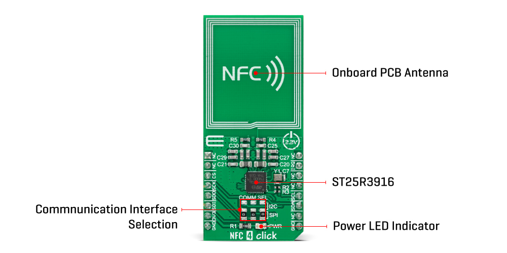
NFC 4 Click is a compact add-on board that contains an NFC transceiver for contactless communication. This board features the ST25R3916, a multi-purpose NFC transceiver supporting passive peer-to-peer functionality and NFC card-emulation mode, as well as NFC reader operation from STMicroelectronics. It features high RF output power to directly drive an antenna etched on the PCB, alongside its tuning circuit, at high efficiency. The ST25R3916 also represents an EMVCo reader fully compliant with ISO 14443A/B, ISO 15693, ISO 18092, Felica, and NFC Forum standards. Thanks to the ST25R3916, this Click board™ provides all the features designers need to quickly market and comply with relevant NFC specifications. This Click board™ represents an ideal solution for rapidly integrating NFC technology in any custom application.
NFC 4 Click is supported by a mikroSDK compliant library, which includes functions that simplify software development. This Click board™ comes as a fully tested product, ready to be used on a system equipped with the mikroBUS™ socket.
NFC 4 Click as its foundation uses the ST25R3916, a high-performance multi-purpose NFC transceiver supporting NFC initiator, NFC target, reader, and card emulation modes from STMicroelectronics. It features high RF output power to directly drive an antenna etched on the PCB, alongside its tuning circuit, at high efficiency. Besides being fully compliant with EMVCo 3.0, it also includes an advanced analog front end and a highly integrated data framing system for ISO 18092 passive and active initiator and target, NFC-A/B (ISO 14443A/B) reader including higher bit rates, NFC-F (FeliCa™) reader, NFC-V (ISO 15693) reader up to 53 kbps, and NFC-A / NFC-F card emulation. Due to this combination of high RF output power and low power modes, this Click board™ is ideally suited for infrastructure NFC applications.

The ST25R3916 features a built-in A/D converter, which input can be multiplexed from different sources used for the diagnostic functions and the low power card detection. The result of the A/D conversion is stored in a register that can be read through the selectable host interface. It also contains a low-power capacitive sensor to detect the presence of a card without switching on the reader field by measuring the amplitude or phase of the antenna signal. Also, an integrated low power RC oscillator and a wake-up timer automatically wake up the ST25R3916 and check for a presence of a tag using one or more techniques of low power detection of card presence (capacitive, phase, or amplitude).
NFC 4 Click communicates with a microcontroller either via an SPI interface or via an I2C interface. The ST25R3916 acts as a slave device on both interfaces, relying on the microcontroller to initiate all communication. The communication selection can be made by positioning SMD jumpers labeled as COMM SEL to an appropriate position. Note that all the jumpers' positions must be on the same side, or the Click board™ may become unresponsive. This Click board™ also features an additional interrupt signal routed on the INT pin of the mikroBUS™ socket to notify the microcontroller of completed commands or external events (e.g., peer device field on).
This Click board™ can be operated only with a 3.3V logic voltage level. The board must perform appropriate logic voltage level conversion before use with MCUs with different logic levels. However, the Click board™ comes equipped with a library containing functions and an example code that can be used, as a reference, for further development.
Specifications:
| Type | RFID/NFC |
| Applications | Can be used for rapidly integrating NFC technology in any custom application |
| On-board modules | ST25R3916 - high-performance multi-purpose NFC transceiver supporting NFC initiator, NFC target, reader, and card emulation modes from STMicroelectronics |
| Key Features | Low power NFC active and passive target modes, low power capacitive and inductive card detection, fully compliant with EMVCo 3.0, noise suppression, selectable communication interfaces, and more |
| Interface | I2C,SPI |
| Compatibility | mikroBUS |
| Click board size | L (57.15 x 25.4 mm) |
| Input Voltage | 3.3V |
PinOut Diagram:
This table shows how the pinout on NFC 4 Click corresponds to the pinout on the mikroBUS™ socket (the latter shown in the two middle columns).
OnBoard Settings And Indicators:
| Label | Name | Default | Description |
|---|---|---|---|
| LD1 | PWR | - | Power LED Indicator |
| JP1-JP2 | COMM SEL | Lower | Communication Interface Selection SPI/I2C: Lower position SPI, Upper position I2C |
NFC 4 Click Electrical Specifications:
| Description | Min | Typ | Max | Unit |
|---|---|---|---|---|
| Supply Voltage | - | 3.3 | - | V |
| RF Speed | - | - | 848 | kbps |
| Operating Temperature Range | -40 | +25 | +105 | °C |
Software Support:
We provide a library for the NFC 4 Click as well as a demo application (example), developed using MikroElektronika compilers. The demo can run on all the main MikroElektronika development boards.
Package can be downloaded/installed directly from NECTO Studio Package Manager(recommended way), downloaded from our LibStock™ or found on Mikroe github account.
Library Description
This library contains API for NFC 4 Click driver.
Key functions:
nfc4_get_mifare_tag_uid- This function reads the UID of a mifare tag.nfc4_write_register- This function writes a desired data to the selected register.nfc4_read_register- This function reads a desired data from the selected register.
Examples description
This example demonstrates the use of NFC 4 Click board by reading MIFARE ISO/IEC 14443 type A tag UID.
void application_task ( void )
{
    uint8_t tag_uid[ 10 ] = { 0 };
    uint8_t uid_len = 0;

    if( NFC4_OK == nfc4_get_mifare_tag_uid( &nfc4, tag_uid, &uid_len ) )
    {
        log_printf( &logger, " Tag UID: " );
        for ( uint8_t cnt = 0; cnt < uid_len; cnt++ )
        {
            log_printf( &logger, "%.2X", ( uint16_t ) tag_uid[ cnt ] );
        }
        log_printf( &logger, "rn" );
        Delay_ms( 500 );
    }
}
The full application code, and ready to use projects can be installed directly from NECTO Studio Package Manager(recommended way), downloaded from our LibStock™ or found on Mikroe github account.
Other mikroE Libraries used in the example:
- MikroSDK.Board
- MikroSDK.Log
- Click.NFC4
Additional notes and informations
Depending on the development board you are using, you may need USB UART click, USB UART 2 click or RS232 click to connect to your PC, for development systems with no UART to USB interface available on the board. The terminal available in all MikroElektronika compilers, or any other terminal application of your choice, can be used to read the message.
MikroSDK:
This Click board™ is supported with mikroSDK - MikroElektronika Software Development Kit. To ensure proper operation of mikroSDK compliant Click board™ demo applications, mikroSDK should be downloaded from the LibStock and installed for the compiler you are using.
For more information about mikroSDK, visit the official page.
Resourcse:
Downloads:
Enter the code in the box below:


