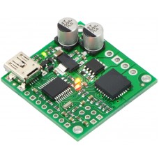
Pololu Jrk 21v3 USB Motor Controller with Feedback
This product has been replaced by the newer version of Pololu #3142
Description
The jrk 21v3 motor controller is a highly configurable brushed DC motor controller that supports four interface modes: USB, logic-level serial, analog voltage, and hobby radio control (RC). The controller can be used with feedback for closed-loop speed or position control, or it can be used without feedback as an open-loop speed control. The continuous output current is approximately 3 A in the recommended operating range of 8–28 V, with derated performance down to 5 V and transient protection to 40 V. The version ships with connectors included but not soldered in, allowing for custom installations.
Overview
The jrk 21v3 is a versatile, general-purpose motor controller that supports a variety of interfaces, including USB. The broad operating range from 5 V to 28 V and continuous output current of 3 A (5 A peak) allow this board to control most small DC brushed motors. Analog voltage and tachometer (frequency) feedback options allow quick implementation of closed-loop servo systems, and a free configuration utility (for Windows) allows easy calibration and configuration through the USB port.
Key improvements over competing products and earlier Pololu motor controllers with feedback include:
- USB connectivity with emulated serial (COM) port allows direct motor control from a PC.
- Ultrasonic PWM to eliminate switching-induced motor shaft hum or whine.
- Robust, high-speed communication protocol with user-configurable error condition response.
- High internal resolution (12 bits) for smooth and flexible calibration to various input and feedback devices.
- Current sensing and limiting.
- Reversed power protection.
- Field-upgradeable firmware.
Note: A USB A to mini-B cable (not included) is required to connect this controller to a computer.
Main Features of the Jrk 21v3
Two closed-loop feedback options:Simple bidirectional control of one DC brush motor.
- 5 V to 28 V operating supply range.
- 3 A maximum continuous current output (5 A peak).
- Four communication or control options:
- USB interface for direct connection to a PC.
- Full-duplex, TTL-level asynchronous serial interface for direct connection to microcontrollers or other embedded controllers.
- Hobby radio control (RC) pulse width interface for direct connection to an RC receiver or RC servo controller.
- 0–5 V analog voltage interface for direct connection to potentiometers and analog joysticks.
-
- 0–5 V analog voltage.
- Frequency/tachometer digital input up to 2 MHz with 1 ms PID period.
(Open-loop control with no feedback also available.)
- Simple configuration and calibration over USB with free configuration program (Windows 8, Windows 7, Vista, and Windows XP compatible).
- Configurable parameters include:
- PID period and PID constants (feedback tuning parameters).
- Maximum current.
- Maximum duty cycle.
- Maximum acceleration.
- Error response.
- Input calibration (learning) for analog and RC control.
- Optional CRC error detection eliminates communication errors caused by noise or software faults.
- Reversed power protection.
- Field-upgradeable firmware.
- Optional feedback potentiometer disconnect detection.
- Comprehensive user’s guide.
Specifications
|
Motor channels: |
1 |
|
Operating voltage: |
5 – 28 V |
|
Continuous output current: |
3 A |
|
Peak output current: |
5 A |
|
Auto-detect baud rate range: |
300 – 115,200 bps |
|
Available fixed baud rates: |
300 – 115,200 bps |
|
Available PWM frequencies: |
20 kHz, 5 kHz |
|
Reverse voltage protection?: |
Yes |
|
USB connector style: |
USB Mini-B |
The jrk 21v3 is the smaller of two jrk motor controllers. For a higher-power version, see the jrk 12v12
Included Hardware
|
|
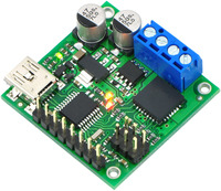
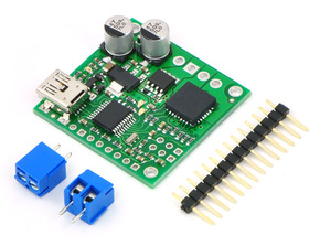
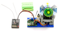
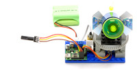
The jrk 21v3 is available in two versions: “fully assembled” with terminal blocks and 0.1″ male header pins pre-installed (left picture above), and connector-free (right picture above). The connector-free version includes a straight 0.1″ breakaway male header strip and two 3.5mm, 2-pin terminal blocks, but these parts are not soldered to the board, which allows for custom installations.
The three mounting holes are intended for use with #2 screws (not included).
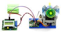
Example Feedback System – 4 Methods of Control
|
|
||||
|
|
Dimensions
| Size: | 1.35" x 1.35" x 0.4"1 |
|---|
General specifications
| Motor driver: | MC33926 |
|---|---|
| Motor channels: | 1 |
| Control interface: | USB; non-inverted TTL serial; RC servo pulses; analog voltage2 |
| Minimum operating voltage: | 5 V |
| Maximum operating voltage: | 28 V |
| Continuous output current per channel: | 3 A |
| Peak output current per channel: | 5 A |
| Current sense: | 0.5 V/A3 |
| Maximum PWM frequency: | 20 kHz |
| Minimum logic voltage: | 4 V4 |
| Maximum logic voltage: | 5 V |
| Reverse voltage protection?: | Y |
| Partial kit?: | Y |
| Version: | original 21v3 (28 V max, 3 A max continuous) |
Notes:
1. Without included hardware.
2. Autodetects baud rates between 300 and 115,200 bps, or can be set to any fixed baud rate in this range.
3. Current readings are converted to a digital number from 0-255.
3. In RC mode, the pulses can be as low as 2V.
Enter the code in the box below:
