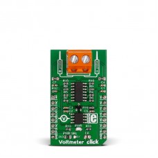
Voltmeter click
The design of the board is based on an OpAmp set up as a differential amplifier with a buffered input.
Two onboard screw terminals (probe+ and probe-) are bringing in the current, which then flows through a row of four resistors. A voltage – proportional to the input charge – is generated across the last two resistors. From there it is sent to the differential amplifier that further intensifies the difference between the two inputs (+/-).
The resulting charge is exactly 33 times lower than the actual measured voltage. It is converted by an onboard 12-bit ADC before being outputted through the mikroBUS™ SPI interface (the firmware in the target board MCU should be set up to multiply the ADC value to get the actual voltage). It is also possible to output the analog value directly through the mikroBUS™ AN pin (useful if the target MCU has a higher resolution ADC).
The board can work with either a 3.3V or a 5V power supply.
Specification:
| Type | Measurements |
| Applications | Measuring DC Voltage from external circuit |
| On-board modules | MCP3201 12-bit ADC, MCP609 CMOS, MAX6106 |
| Key Features | Measurement range: 0-24Vdc, 12-bit ADC |
| Key Benefits | Measures both positive and negative charges, Possible to measure analog values directly |
| Interface | Analog,SPI |
| Input Voltage | 3.3V or 5V |
| Compatibility | mikroBUS |
| Click board size | M (42.9 x 25.4 mm) |
Features and usage notes
Voltmeter click is designed to measure Direct Current only, and has a measurement range from 0 to 24V (it’s possible to measure both positive and negative charges).
The design of the board is based on an OpAmp set up as a differential amplifier with a buffered input.
Two onboard screw terminals (probe+ and probe-) are bringing in the current, which then flows through a row of four resistors (R1, R2, R14, R15). A voltage – proportional to the input charge – is generated across the last two resistors (R14, R15). From there it is sent to the differential amplifier that further intensifies the difference between the two inputs (+/-).
The board can work with either a 3.3V or a 5V power supply. This is configured by soldering the onboard PWR SEL jumper in the appropriate position. Note that it’s not possible to power the board with the same current you wish to measure.
Programming
The following code snippet shows how to send temperature readings from Voltmeter click to a TFT display.
 1 void system_setup( void );
 2 unsigned int getADC( void );
 3
 4 void main()
 5 {
 6   system_setup();
 7
 8   while (1)
 9   {
10
11     voltage = 0;
12
13     measurement = getADC() / 2;    // Get ADC result
14     voltage = (measurement - calibration) * 33.3405;
15
16     FloatToStr(voltage, txt);
17
18     UART1_Write_Text(txt);
19     UART1_Write(32);
20     UART1_Write_Text("mV");
21     UART1_Write(13);
22     UART1_Write(10);
23
24     delay_ms(1000);
25   }
26 }
27
28 void system_setup( void )
29 {
30   GPIO_Digital_Output( &GPIOD_BASE, _GPIO_PINMASK_13 );
31
32   UART1_Init(9600);               // Initialize UART module at 9600 bps
33   Delay_ms(300);                  // Wait for UART module to stabilize
34   UART1_Write_Text( "UART Initializedrn" );
35
36   voltage = 0;
37   sum = 0;
38   measurement = 0;
39   calibration = 0;
40
41   Chip_Select = 1;
42
43   // SPI
44   SPI3_Init_Advanced( _SPI_FPCLK_DIV16, _SPI_MASTER | _SPI_8_BIT |
45                       _SPI_CLK_IDLE_LOW | _SPI_SECOND_CLK_EDGE_TRANSITION |
46                       _SPI_MSB_FIRST | _SPI_SS_DISABLE | _SPI_SSM_ENABLE |
47                       _SPI_SSI_1, &_GPIO_MODULE_SPI3_PC10_11_12 );
48   Delay_ms(300);
49   UART1_Write_Text( "SPI Initializedrn" );
50
51   calibration = getADC() / 2;
52 }
Code examples that demonstrate the usage of Voltmeter click with MikroElektronika hardware, written for mikroC for ARM, AVR, dsPIC, FT90x, PIC and PIC32 are available on Libstock.
Downloads
Enter the code in the box below:


