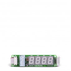
Serial 7-seg Display Board
The Serial 7-seg Display Board features a compact, serial input/output common-cathode display driver MAX7219 used to interface MCUs to 7-segment numeric LED displays via SPI interface. The chip includes a BCD code-B decoder, multiplex scan circuitry, segment and digit drivers and 8x8 static RAM for storing digits. Display drivers are connected to 4 common-cathode LED displays.
The board is equipped with a flat cable ending with IDC10 female header connector, which is compatible with all mikroElektronika development boards. It features four 7-segment digits arranged in a single row.
How to connect the board?
The additional board is connected to a development system via an IDC10 connector on the board and a 2x5 connector on one of the development system’s ports. It is necessary to define in the program, to be loaded into the microcontroller, which port will be used for SPI communication.
The position of SMD jumpers depends on the development system in use. These jumpers are placed in the position marked PIC by default. It means that the board is ready to be used with PIC development systems. If you want to use it with AVR/8051 development systems, it is necessary to unsolder jumpers from the PIC position and resolder them in the AVR/8051 position.
The Serial 7-Seg Display additional board is powered with the 5V power supply from the development system it is connected to.
How does the board operate?
In order to use this additional board, it is necessary to load a .hex code into the microcontroller on the development system. Find examples of .hex code that may be loaded into the microcontroller on our website:
http://www.mikroe.com/eng/products/view/162/serial-7-seg-display-board/
As a result of the .hex code loading, the development system starts communication with the additional board via a Serial Peripheral Interface (SPI).
Displaying digits
Displaying digits is enabled by the time-division multiplexing. All the operations related to multiplexing and displaying digits are performed by using the MAX7219 circuit provided on the additional board.
The time-division multiplexing of a 7-segment display is based on fast turning the display segments on/off in such a manner that one gets an impression that all eight digits are active at the same time. The MAX7219 circuit feeds digit segments with a signal via pins marked SEGxx, whereas pins marked DIGx are used to select one of four displays to show the appropriate number.
Specification
| Type | LED Segment |
| Applications | Board enables you to easily add four 7-segment digits to your device, while saving microcontrolller pins and processing power |
| On-board modules | MAX7219 display driver, 4 common-cathode LED displays |
| Key Features | Easy adjustment of connector pinout using DIP switches. Flat cable with IDC10 female header connector |
| Key Benefits | IDC10 connector enables easy connection with peripheral devices |
| Interface | SPI |
| Input Voltage | 5V |
| Compatibility | IDC10 |
Downloads
Enter the code in the box below:


