Proximity 6 click
With its high sensitivity and signal to noise ratio, this Click board™ is ideally suited for a range of applications that rely on accurate and reliable proximity detection. It can be used for proximity activated surveillance systems, equipment lid closing, object proximity detection, simple gesture activated HID interface, and other similar applications which rely on an accurate object proximity detection.
How does it work?
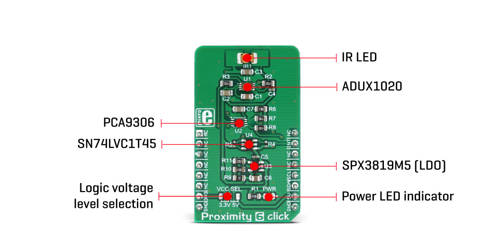
The main sensor IC on the Click board™ is the ADUX1020, a photometric sensor for gesture and proximity detection, from Analog Devices. Among other sections, this IC contains a LED driver, used to drive an externally connected LED, which provides feedback for the ADUX1020 sensory sections. Therefore, the LED should be chosen so that its spectrum matches the spectral sensitivity of the on-chip light sensor. For this reason, the Click board™ is equipped with the narrow beam LED from OSRAM with its spectral response characteristic peaking at 860nm, which is a perfect choice for this application.
 The proximity detection consists of sending a pulse to the LED while measuring the response of the reflected light. Each data sample is constructed from the sum of a configurable number of individual pulses. There can be up to 64 such pulses. Additional intersample averaging can be applied to these values for the improved noise reduction, and the results are stored in the FIFO buffer, from where the MCU can read them via the standard I2C interface. Most of the parameters are user configurable, such as the sampling frequency, a number of pulses, averaging parameters and more. More in-depth information about the registers can be found in the ADUX1020 datasheet.
Aimed towards the low consumption market, the ADUX1020 uses a rather low voltage range, between 1.7V and 1.9V. Since the most of the MCUs use either 3.3V or 5V, the Click board™ has to be equipped with the supporting circuitry, which is used to convert the MCU signal levels to levels acceptable for the ADUX1020 IC. This supporting circuitry consists of a small LDO that provides 1.8V for the proper ADUX1020 IC operation, as well as the bidirectional I2C voltage level translator IC (PCA9306), and a single bit, dual voltage level translator IC (SN74LVC1T45), used for a proper conversion of the logic voltage levels. These level shifting ICs are supplied with the referent 1.8V from the LDO from one side, and selectable VCC voltage from the other side. VCC voltage can be selected between 3.3V and 5V, by using the SMD jumper labeled as VCC SEL. This allows both 3.3V and 5V MCUs to be interfaced with the ADUX1020 IC.
Proximity 6 click offers an interrupt output pin that can be used to trigger an interrupt on the host MCU. The ADUX1020 IC interrupt engine allows several interrupt sources, which can be used to trigger a state change on the INT pin. These sources include configurable FIFO buffer threshold, two pairs of proximity detection interrupts (proximity OFF and proximity ON), sample interrupt, and even a watchdog interrupt. The INT pin itself is highly configurable. For example, it can be set to be either active HIGH or active LOW, or it can be set to output the internal clock of the ADUX1020 IC. When asserted, this pin triggers an MCU interrupt, informing it that the configured interrupt event has occurred. The MCU can then read the desired register output, not having to poll it constantly, which saves both MCU cycles and power. The INT pin is routed via the level shifting IC to the mikroBUS™ INT pin.
As already mentioned, detailed information on the ADUX1020 IC registers can be found in the datasheet. However, MikroElektronika provides a library that contains functions compatible with the MikroElektronika compilers, which can be used for a simplified programming of the Proximity 6 click. The library also contains an example application, which demonstrates their use. This example application can be used as a reference for custom designs.
Specifications
| Type | Proximity |
| Applications | It can be used for proximity activated surveillance systems, equipment lid closing, object proximity detection, simple gesture activated HID interface, and other similar applications which rely on an accurate object proximity detection. |
| On-board modules | ADUX1020, a photometric sensor for gesture and proximity detection, from Analog Devices; PCA9306, a bidirectional I2C voltage level translator IC from Texas Instruments; SN74LVC1T45, a single-Bit dual-supply bus transceiver from Texas Instruments. |
| Key Features | Accurate proximity detection, simple gesture detection, integrated data aggregation algorithm, high sensitivity, low power consumption, can be interfaced to both 3.3V and 5V MCUs, and more. |
| Input Voltage | 3.3V,5V |
| Click board size | M (42.9 x 25.4 mm) |
Pinout diagram
This table shows how the pinout on Proximity 6 click corresponds to the pinout on the mikroBUS™ socket (the latter shown in the two middle columns).
Onboard settings and indicators
| Label | Name | Default | Description |
|---|---|---|---|
| JP1 | VCC SEL. | Left | Logic voltage level selection: left position 3V3, right position 5V |
| LD1 | PWR | Power indication LED |
Software support
We provide a library for Proximity 6 click on our Libstock page, as well as a demo application (example), developed using MikroElektronika compilers and mikroSDK. The provided click library is mikroSDK standard compliant. The demo application can run on all the main MikroElektronika development boards.
Library Description
This library provides generic functions for working with the Click board™.
Key functions:
uint8_t proximity6_writeReg( uint8_t register_address, uint16_t transfer_data )- The function writes 16-bit data to the register.uint8_t proximity6_setMode( uint8_t selectMode )- The function puts the device in the desired operating mode.void proximity6_getPosition( uint8_t *position )- The function reads proximity data and checks from which side the object (body) effects on the sensor.uint8_t proximity6_displayData( uint8_t *dataValue, uint8_t setResolution )- The function shows proximity data values in determined resolution as graphics view.
Examples Description
The application is composed of three sections:
- System Initialization - Initializes peripherals and pins.
- Application Initialization - Sets the registers in a default state and configures the device to work in proper operating mode (Proximity Mode).
- Application Task - (code snippet) - Example can show the data register values as graphic view in desired resolution. Also can determine from which side the object (body) effects on the sensor and logs results on USB UART. Results will be shown only when one or more data registers are updated with the new value (sensor detects the change).
void applicationTask()
{
 proximity6_logPositionRes();
}
Additional functions:
void proximity6_logGraphicRes()- The function logs on USB UART results from the data proximity registers as graphic view.void proximity6_logPositionRes()- The function logs on USB UART the position of the object which affects the sensor.
The full application code, and ready to use projects can be found on our Libstock page.
Other mikroE Libraries used in the example:
- I2C
- UART
Additional notes and information
Depending on the development board you are using, you may need USB UART click, USB UART 2 click or RS232 click to connect to your PC, for development systems with no UART to USB interface available on the board. The terminal available in all MikroElektronika compilers, or any other terminal application of your choice, can be used to read the message.
mikroSDK
This click board is supported by mikroSDK - MikroElektronika Software Development Kit. To ensure proper operation of mikroSDK compliant click board demo applications, mikroSDK should be downloaded from the LibStock and installed for the compiler you are using.
For more information about mikroSDK, visit the official page.
Downloads
mikroBUS™ Standard specificationLibstock: Proximity 6 click library
Enter the code in the box below:


