NB IoT 4 Click
NB IoT 4 Click is a compact add-on board that contains a cellular IoT-based module with integrated eSIM for global data connectivity. This board features the C1-RM, a three-band NB-IoT IoT/2G wireless communication module supporting Band 3, 5, and 8 mainly applied to low power data transmission service from Cavli Wireless. The module also supports the 3GPP Release 13 standard and meets almost all M2M requirements because of its ultra-small size. It uses low-power technology with a Standby power consumption of less than 1mA, where deep sleep mode can be as low as 5uA. It also offers external interfaces, protocol stacks (providing great convenience for your applications), and a complete range of SMS and data transmission services to meet client-side demands. This Click board™ is suitable for many IoT applications, such as smart metering, intelligent wearables, security and asset tracking, home appliances, environmental monitoring, and more.
NB IoT 4 Click is supported by a mikroSDK compliant library, which includes functions that simplify software development. This Click board™ comes as a fully tested product, ready to be used on a system equipped with the mikroBUS™ socket.
NB IoT 4 Click as its foundation uses the C1-RM, the LTE CAT NB-IoT intelligent cellular module with 2G fall-back option based on 3GPP Release 13 with integrated eSIM feature for global data connectivity from Cavli Wireless. It supports a broad range of frequency bands such as NB-IoT: B3/B5/B8/B20/B28 and GPRS: GSM850/EGSM900/DCS1800/PCS1900 with automatic search of frequency bands and the band selection by AT command. It also provides several interfaces and protocol stacks such as UDP/TCP/CoAP/LWM2M and others, allowing data and SMS transmission using NB technology, making it the perfect choice for building various IoT solutions.

This module is specially designed for countries with less than 100% NB-IoT coverage or upcoming NB-IoT network, where LPWAN deployments can happen in 2G and switch to NB-IoT when the network is ready. The integrated eSIM feature ensures that the module can be deployed across the globe.
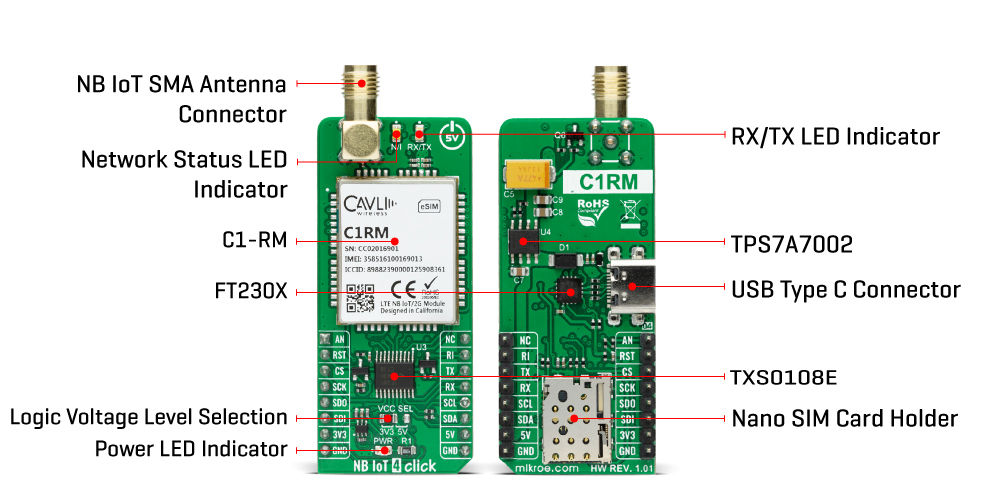
The C1-RM communicates with MCU using the UART interface with commonly used UART RX and TX pins as its default communication protocol for exchanging AT commands operating at 115200 bps by default configuration to transmit and exchange data with the host MCU. It is also equipped with a USB type C connector, which allows the module to be powered and configured by a personal computer (PC) using FT230X, a compact USB to a serial UART interface bridge designed to operate efficiently with USB host controllers. With the help of FT230X, it is possible to access a debug serial port of C1-RM to upgrade firmware and check the log information. It also possesses the RX/TX blue LED indicator that indicates whether the bridge is in RX or TX mode. The users can also use other interfaces such as SPI or I2C to configure the module and write the library by themselves.
The RI pin routed on the INT pin of the mikroBUS™ represents the external interrupt pin used for waking up the device from a power-saving mode, while the RST pin on the mikroBUS™ socket can perform Hardware Reset function by putting this pin in a logic low state. Next to these pins, this Click board™ also provides a white LED indicator labeled as N/I to indicate the status of network communication in addition to an analog-to-digital conversion pin routed on the AN pin of the mikroBUS™ socket, which can realize external temperature monitoring and can read voltage through AT command.
NB IoT 4 Click has the SMA antenna connector with an impedance of 50Ω used for connecting the appropriate antenna that Mikroe has in its offer. Besides the NB IoT SMA connector, this Click board™ also has a Nano-SIM card slot that provides multiple connections and interface options.
This Click board™ can operate with both 3.3V and 5V MCUs. A proper logic voltage level conversion is performed by appropriate voltage level translator TXS0108E, while the on-board LDO, the TPS7A7002, ensures that the recommended voltage levels power module. However, the Click board™ comes equipped with a library containing easy-to-use functions and an example code that can be used, as a reference, for further development.
The customers can submit a ticket to the official Cavli Wireless Support page for all additional support questions such as eSIM card provisioning.
Specifications:
| Type | LTE IoT |
| Applications | Can be used for many IoT applications, such as smart metering, intelligent wearables, security and asset tracking, home appliances, environmental monitoring, and more |
| On-board modules | C1-RM - LTE CAT NB-IoT intelligent cellular module with 2G fall-back option based on 3GPP Release 13 with integrated eSIM feature for global data connectivity from Cavli Wireless |
| Key Features | Ultra-low power consumption, multi-band NB-IoT module, high performance, built-in eSIM, wake-up interrupt, and more. |
| Interface | Analog,I2C,SPI,UART,USB |
| Compatibility | mikroBUS |
| Click board size | L (57.15 x 25.4 mm) |
| Input Voltage | 3.3V or 5V |
PinOut Diagram:
This table shows how the pinout on NB IoT 4 Click corresponds to the pinout on the mikroBUS™ socket (the latter shown in the two middle columns).
OnBoard Settings And Indicators:
| Label | Name | Default | Description |
|---|---|---|---|
| LD1 | PWR | - | Power LED Indicator |
| LD3 | RX/TX | - | RX/TX LED Indicator |
| LD4 | N/I | - | Network Status LED Indicator |
| JP1 | VCC SEL | Left | Logic Level Voltage Selection 3V3/5V: Left position 3V3, Right position 5V |
NB IOT 4 Click Electrical Specifications:
| Description | Min | Typ | Max | Unit |
|---|---|---|---|---|
| Supply Voltage | 3.3 | - | 5 | V |
| Operating Frequency Range (Uplink) | 703~748 | - | 1850~1910 | MHz |
| Operating Frequency Range (Downlink) | 758~803 | - | 1930~1990 | MHz |
| Operating Temperature Range | -20 | +25 | +70 | °C |
Software Support:
We provide a library for the NB IoT 4 Click as well as a demo application (example), developed using MikroElektronika compilers. The demo can run on all the main MikroElektronika development boards.
Package can be downloaded/installed directly from NECTO Studio Package Manager(recommended way), downloaded from our LibStock™ or found on Mikroe github account.
Library Description
This library contains API for NB IoT 4 Click driver.
Key functions:
nbiot4_cfg_setup- Config Object Initialization function.nbiot4_init- Initialization function.nbiot4_default_cfg- Click Default Configuration function.
Example description
Application example shows device capability to connect network and send SMS messages using standard "AT" commands.
void application_task ( void )
{
    switch ( example_state )
    {
        case NBIOT4_CONFIGURE_FOR_CONNECTION:
        {
            if ( !nbiot4_configure_for_connection() )
                example_state++;
            break;
        }
        case NBIOT4_WAIT_FOR_CONNECTION:
        {
            nbiot4_wait_to_connect( );
            example_state++;
            break;
        }
        case NBIOT4_CHECK_CONNECTION:
        {
            if ( !nbiot4_check_connection() )
                example_state++;
            break;
        }
        case NBIOT4_CONFIGURE_FOR_SMS:
        {
            if ( !nbiot4_configure_for_sms() )
                example_state++;
            break;
        }
        case NBIOT4_MESSAGES:
        {
            nbiot4_send_meesage();
            break;
        }
        default:
        {
            log_error( &logger, " Unknown example state." );
            Delay_ms( 500 );
        }
    }
}
The full application code, and ready to use projects can be installed directly from NECTO Studio Package Manager(recommended way), downloaded from our LibStock™ or found on Mikroe github account.
Other Mikroe Libraries used in the example:
- MikroSDK.Board
- MikroSDK.Log
- Click.NBIoT4
Additional notes and informations
Depending on the development board you are using, you may need USB UART click, USB UART 2 click or RS232 click to connect to your PC, for development systems with no UART to USB interface available on the board. The terminal available in all MikroElektronika compilers, or any other terminal application of your choice, can be used to read the message.
MikroSDK:
This Click board™ is supported with mikroSDK - MikroElektronika Software Development Kit. To ensure proper operation of mikroSDK compliant Click board™ demo applications, mikroSDK should be downloaded from the LibStock and installed for the compiler you are using.
For more information about mikroSDK, visit the official page.
Resources:
Downloads:
NB IoT 4 click example on Libstock
Enter the code in the box below:


