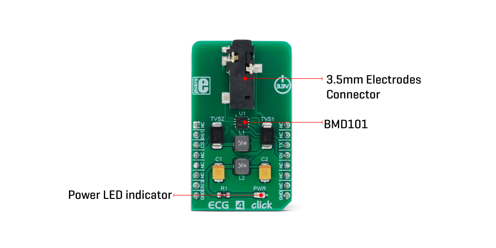
ECG 4 Click
Note: ECG 4 is a development and prototyping tool. It is not intended to be used for medical treatment of patients and other life-critical applications!
The BMD101 SoC integrates all the necessary components, so there are very few external parts required. An analog front-end section of the BMD101 SoC features an HP filter, a 16-bit A/D converter, and a low-noise amplifier (LNA), allowing it to properly sample bio-signals, which are in magnitudes of µV. The raw data is further processed by powerful filtering DSPs, allowing clean and accurate HR and ECG readings over the UART interface. This makes the ECG 4 click an ideal solution for development of a wide range of single-channel ECG and HR-related applications, including heart rate monitoring applications, fitness applications, ECG bio-authentication, and similar.
What is ECG?
ECG or the electrocardiography is a process of recording the electrical activity of the heart over time, using electrodes placed on the body. These electrodes detect small electrical changes that arise from the electrophysiological pattern of the heart muscle. ECG 4 click is used to record a single-channel electrocardiogram. The electrodes can be attached to the ECG 4 click via the 3.5mm jack. The ECG 4 click uses a three-electrode system, where two electrodes are connected to the positive and negative differential inputs of the BMD101 (SEP and SEN pins), while the third electrode is connected to the GND. The Click board™ can be used with electrodes such as these: ECG/EMG cable, and ECG/EMG electrodes. In this case, the white electrode is the GND electrode. You can watch a video about the electrodes and their placement, or read about it in this Let’s learn blog article.
How does it work?
The main component of the ECG4 click is the BMD101, a highly integrated specialized bio-signal sensing System-on-Chip (SoC), from NeuroSky, a company specialized in the production of heart monitoring-related ICs and applications. This IC is the third generation of bio-sensors from this company and it features the complete HR and ECG system on a chip: the analog front-end (AFE) section contains very precise and low-noise instrumentation amplifier (LNA), which allows very low bio-signals generated by the heart to be amplified enough for the 16-bit ADC to be able to sample them.

These voltage impulses are weak by nature and in the range of just a few millivolts, even microvolts. Therefore, any external interferences might obscure them. These interferences might be induced in the human body itself, or they might appear as the result of the activity of other muscles, such as skeletal muscles. Therefore, the input signal from the electrodes is processed by several filtering sections, both in the analog (HP filter at the input), and digital domain (LP filter at 100 Hz and BP filter for removing the 50/60 Hz hum from the mains). However, the correct placement of the measurement electrodes is crucial for accurate readings. More about the electrodes and their placement can be found in the aforementioned blog article.
ECG 4 click allows several types of electrodes to be used. It supports both stainless-steel and silver-chloride electrode types. The electrodes are used to perform differential measurement of the voltage generated by the heart. Therefore, the heart can be monitored from a single plane only - the coronal plane. However, this is quite enough for the fitness, heart rate monitoring and similar applications. The 3.5mm electrodes connector is further protected by two TVS diodes, which prevent electrostatic discharge (ESD) through the SoC, and the Click board™ itself. The absence of the electrodes is detectable by the BMD101, which turns the sensor OFF if there is approximately 19 to 25 MΩ between the electrodes.
The BMD101 SoC uses the UART interface for the communication. The UART interface works at 57600 baud rate and has 64 bytes of TX FIFO. It uses the 8-1-1 configuration (1 start bit, 8 data bits, 1 stop bit), allowing communication beyond the host microcontroller. The UART interface could be used with any of the USB to UART clicks, allowing the PC or smartphone to process and display the HR and ECG data. More information about the UART interface can be found in the datasheet of the BMD101 SoC. However, provided mikroSDK library offers ready-made functions which speed up the software development process.
There is a CS pin on the BMD101 SoC, which is routed to the CS pin of the mikroBUS™. This pin should be set to a HIGH logic level in order to activate the internal power supply. The RESET pin is routed to the mikroBUS™ RST pin. Setting it to a LOW logic level will trigger a RESET of the BMD101.
This Click board™ is designed to be interfaced with 3.3V MCUs. A proper voltage translator circuit is required if using it with 5V MCUs.
Specifications
| Type | Biomedical |
| Applications | ECG 4 click is an ideal solution for development of heart rate monitoring applications, fitness applications, for the ECG bio-authentication, and similar applications. |
| On-board modules | BMD101, a highly integrated specialized bio-signal sensing System-on-Chip (SoC), from NeuroSky. |
| Key Features | ESD and EMI protection of the inputs, compatible with several types of electrodes, electrode absence detection, a flexible UART-based interface, signal conditioning reduces influence of movement artifacts, simplified design with the complete bio-sensing System-on-Chip (SoC). |
| Interface | UART |
| Input Voltage | 3.3V |
| Click board size | M (42.9 x 25.4 mm) |
Pinout Diagram
This table shows how the pinout on ECG 4 Click corresponds to the pinout on the mikroBUS™ socket (the latter shown in the two middle columns).
Onboard Settings And Indicators
| Label | Name | Default | Description |
|---|---|---|---|
| PWR | PWR | - | Power LED indicator |
| CN1 | 3.5mm JACK | - | 3.5mm electrodes connector |
Software Support
We provide a library for the ECG 4 Click on our LibStock page, as well as a demo application (example), developed using MikroElektronika compilers. The demo can run on all the main MikroElektronika development boards.
Library Description
The library performs the ECG and Real-time Heart Rate measurements. For more details check documentation..
Key functions:
void ecg4_response_handler_set( void ( *handler )( uint8_t*, uint8_t*, uint8_t*, uint8_t* ) )- Function sets handler on the function that should be performed, for example, function for results logging.void ecg4_uart_isr( void )- Function performs the uart interrupt routine, reads a data from uart rx buffer and makes a response from the BMD101 device.T_ECG4_RETVAL ecg4_responseReady( void )- Function returns 1 when response is ready for reading, or 0 if is not ready.
Examples description
The application is composed of the three sections :
- System Initialization - Initializes peripherals and pins.
- Application Initialization - Initializes UART interface, performs a reset of the device and powers up control of Low Drop Out (LDO).
- Application Task - (code snippet) - Always checks does response ready and, when is ready, processes a response. Note : The Sound library is used to play sound on buzzer every time when R interval on the ECG signal happened. The Sound Play command can make a delay time which is necessary for play command to be performed. If you don't need to make sound on buzzer, please disable the Sound Init and Sound Play functions.
void applicationTask()
{
    resp_ready = ecg4_responseReady();

    if (resp_ready == _ECG4_RESPONSE_READY)
    {
        processResponse();
    }
}
Additional Functions :
- interrupt - Always checks does new data ready for reading from uart rx buffer, and if is it true reads one byte data from uart and makes a response sequence.
- plotData - Sends a desired data (Raw Data) to the serial plotter.
- logData - Sends data to the uart terminal and shows results.
- makeResponse - Pars a response to the buffer.
- processResponse - Processes a parsed response and makes a decide where response will be showed.
The full application code, and ready to use projects can be found on our LibStock page.
Other mikroE Libraries used in the example:
ConversionsUARTSound
Additional notes and informations
Depending on the development board you are using, you may need USB UART click, USB UART 2 click or RS232 click to connect to your PC, for development systems with no UART to USB interface available on the board. The terminal available in all MikroElektronika compilers, or any other terminal application of your choice, can be used to read the message.
MIKROSDK
This click board is supported with mikroSDK - MikroElektronika Software Development Kit. To ensure proper operation of mikroSDK compliant click board demo applications, mikroSDK should be downloaded from the LibStock and installed for the compiler you are using.
For more information about mikroSDK, visit the official page.
Downloads
Enter the code in the box below:


