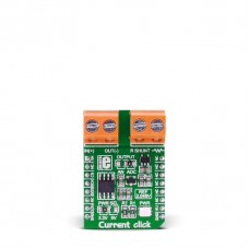
Current click
Current click is an add-on board used for measurement of electric current. It features INA196 current shunt monitor, MCP3201 12-bit ADC, MAX6106 voltage reference as well as two screw terminals. The click is designed to run either 3.3V or 5V power supply. It communicates with the target microcontroller over SPI interface with additional functionality provided by the AN pin on the mikroBUS™ line.
How it works
Current click serves as the current measurement device. The board receives current from the output circuit connected to IN(+) and OUT(-) pins of the first screw terminal. INA196 IC converts this current into a voltage. The second screw terminal is used for the external shunt.
In order to measure current values in various bands, you need to provide the shunt of the appropriate value.
Current click can be used for DC Current measurement in the range of 2-2048mA depending on shunt resistor.
Four shunts with different values are provided in the package.
SMD Jumpers
Current click communicates with the main board microcontroller via SPI interface (using ADC) or via AN line (directly connected to the microcontroller AN pin) depending on the position of the J1 SMD jumper. This jumper is soldered in ADC position. The zero-ohm SMD jumper (J1) is used to select whether 3.3V or 5V power supply is used. Jumper J1 is soldered in 3.3V position by default.
Key features
- INA196 current shunt monitor
- MCP3201 12-bit ADC
- MAX6106 voltage reference
- SPI interface
- 3.3V or 5V power supply
Specification
| ype | Current sensor |
| Applications | Board is an excellent choice for current measurement in wide ranges of values, from 2mA to 2048mA (depending on the connected shunt) |
| On-board modules | INA196 current shunt monitor, MCP3201 12-bit ADC, MAX6106 voltage reference |
| Key Features | Four shunts provided in the package: 0.05Ω, 0.2Ω, 1Ω and 10Ω |
| Key Benefits | Complete current sense solution. Supports bandwidth up to 500kHz |
| Interface | Analog,SPI |
| Input Voltage | 3.3V or 5V |
| Compatibility | mikroBUS |
| Click board size | M (42.9 x 25.4 mm) |
Downloads
mikroBUS™ Standard specification
LibStock: Current click library
Pinout diagram
This table shows how the pinout on Current click corresponds to the pinout on the mikroBUS™ socket (the latter shown in the two middle columns).
Programming
Code examples for Current click, written for MikroElektronika hardware and compilers are available on Libstock.
Code snippet
The following code snippet shows main function, which initializes SPI and graphic interface, and then performs processing of the measurements periodically.
01 void main() {
02  // Draw Graphical Frame
03  DrawFrame();
04
05  measurement = 0;                 // Initialize the measurement variable
06  range_flag = 0;                  // Initialize the out of range flag
07
08  // Set chip select pin to be output
09  GPIO_Digital_Output(&GPIOD_BASE, _GPIO_PINMASK_13);
10  Chip_Select = 1;                 // Deselect MCP3201
11
12  // Initialize SPI3 module at 500kHz, data sampled at the middle of interval
13  SPI3_Init_Advanced(_SPI_FPCLK_DIV128, _SPI_MASTER  | _SPI_8_BIT |
14                     _SPI_CLK_IDLE_LOW | _SPI_FIRST_CLK_EDGE_TRANSITION |
15                     _SPI_MSB_FIRST | _SPI_SS_DISABLE | _SPI_SSM_ENABLE | _SPI_SSI_1,
16                     &_GPIO_MODULE_SPI3_PC10_11_12);
17
18  TFT_Set_Pen(CL_WHITE, 1);
19  TFT_Set_Brush(1, CL_WHITE, 0, LEFT_TO_RIGHT, CL_WHITE, CL_WHITE);
20
21  TFT_Write_Text("I[mA] = ", 55, 110);   // Display string on TFT
22
23  while (1) {
24    measurement = getADC();        // Get ADC result
25    ProcessValue(measurement);     // Process and display current value
26    Delay_ms(250);                 // Wait 250ms
27  }
28
29 }
Enter the code in the box below:


