Cap Touch click
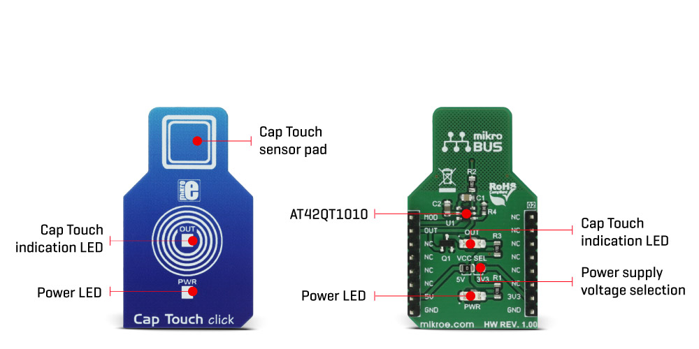
Cap Touch click is a capacitive touch sensing button, integrated on a click board™. It can be activated by touch. This click can sense touch even through plastic, wood, or other dielectric materials, which can be used to protect the surface of the PCB and the sensor pad trace itself. Unlike the mechanical button, the capacitive touch button lasts much longer, it is not prone to damage and wear over time and it is very reliable.
Capacitive buttons are a very popular method of powering up various devices. Besides the aforementioned benefits, having a touch sensitive button on a device allows for a compact design, opens possibilities for various kinds of human-machine interface and - it looks good and modern, especially if accompanied by a LED that turns on when activated, just like the one on Cap Touch click. Cap Touch click can find its place among many applications - for touch activated lighting controls, touch activated control panels, toys and any other applications that need a switch or a button.
How does it work?
Although it looks simple at first glance, capacitive touch sensing is not an easy task. There are many parameters that need to be sampled, filtered, compared and processed before positive touch detection is confirmed. To make this possible, Cap Touch click utilizes the AT42QT1010, a single-key QTouch® touch sensor IC from Microchip. This IC has some advanced features such as the self-calibration, auto drift compensation, noise filtering and proprietary QTouch® technology, based on the patented charge-transfer method. These features enable Cap Touch click exhibit very reliable and accurate touch detection.
Capacitive touch sensing is based on detecting a change in capacitance, due to the influence of a foreign object. Basically, the capacitance of the sensor, also known as the antenna, is measured and monitored and if a significant change occurs, after processing by the detection integrator, a touch event is acknowledged. To successfully perform the detection, many routing requirements need to be met, as the relation between the sensing elements in position and size is crucial. Cap Touch click is designed with these requirements in mind, so it could successfully detect a touch.
This IC uses short bursts to monitor the capacitance and it features three modes of operation: Fast mode, Low Power mode and SYNC mode. Switching between Fast and Low Power mode is done by pulling the SYNC/MODE pin, routed to the mikroBUS™ PWM pin, to a HIGH or LOW logic level, respectively:
- Fast mode yields the fastest detection time, yet it uses the most power, as the device continuously sends measuring bursts, with about 1ms of delay between them. The device will work in this mode if the PWM pin stays permanently at HIGH logic level.
- Low Power mode will send measurement bursts with about 80mS delay in between, significantly lowering the power consumption, as well as the responsiveness of the device. However, when a touch is detected, the device will enter the Fast mode again, allowing the detection integration to detect a valid touch event. The device will work in Low Power mode if the PWM pin stays permanently at LOW logic level.
- SYNC mode is used to control the measurement bursts timing by the clock signal provided on the PWM pin. It is used to reduce crosstalk when using more devices, or to enhance noise immunity from low-frequency sources, such as 50Hz or 60Hz mains signals.

The output of the device is routed to the INT pin of the mikroBUS™. The output pin is active high - on a valid detection it will be set to a HIGH logic level. The output will stay at the HIGH level as long as the touch event is active (touch hold) and will be terminated by the Max On duration feature - a timer that is set to about 60 seconds. If the event is terminated by the Max On duration feature, the device will be recalibrated. The Max On duration feature is normally used to resolve issues when the button detects an event for too long. If an object obstructs the sensor pad - e.g. when a protective plastic layer is added, this feature will recalibrate the sensor so it accommodates for this plastic layer.
After every power on cycle, the device will recalibrate itself. It will take some time, so it should be taken into a consideration when building custom applications. MikroElektronika provides libraries and the demo application, that can be used as a reference for any future designs.
The output of this device is too weak to drive a LED. Yet, a touch button is not good without the LED or other indication of its state. In order to drive a LED, Cap Touch click is equipped with the N-type MOSFET transistor, which is activated by the output pin of the AT42QT1010 IC. It can drive one red LED without a problem.
The onboard SMD jumper labeled as VCC SEL is used to select the operating voltage of the device. It is capable of working with both 3.3V and 5V capable MCUs. Besides PWM pin, used for mode selection and the INT pin, used to signal the button state to the MCU, no other lines of the mikroBUS™ are used.
Specifications
| Type | Capacitive |
| Applications | It can be used for touch activated lighting controls, touch activated control panels, toys and any other applications that need a switch or a button. |
| On-board modules | AT42QT1010, a single-key QTouch® touch sensor IC from Microchip |
| Key Features | Patented QTouch® sensing technology allows for low power consumption, auto calibrating and detection integration algorithms which improve touch sensing quality, Max ON duration for improved obstacle problem handling. |
| Interface | GPIO |
| Input Voltage | 3.3V or 5V |
| Click board size | M (42.9 x 25.4 mm) |
Pinout diagram
This table shows how the pinout on Cap Touch click corresponds to the pinout on the mikroBUS™ socket (the latter shown in the two middle columns).
Onboard settings and indicators
| Label | Name | Default | Description |
|---|---|---|---|
| LD1 | PWR | - |
Power LED Indicator |
| JP1 | VCC SEL | Left | Power Supply Voltage Selection |
| OUT | OUT | - | Touch Button Status LED Indicator |
Software support
We provide a library for Cap Touch click on our LibStock page, as well as a demo application (example), developed using MikroElektronika compilers and mikroSDK. The provided click library is mikroSDK standard compliant. The demo application can run on all the main MikroElektronika development boards.
Library Description
Initializes and defines GPIO driver and driver's functions. This function determines in which mode Cap Touch will works. The click can use a PWM library for setting the click in sync mode. Driver library also checks OUT pin state.
Key functions:
void captouch_setFastMode(void);- Function sets fast mode
void captouch_setLowPowerMode(void);- Function sets low power mode
uint8_t captouch_getOut(void);- Function gets state of OUT pin
Examples Description
The demo application is composed of three sections:
- System Initialization - Initializes peripherals and pins.
- Application Initialization - Initializes click driver.
- Application Task - Sets the click on fast mode or low power mode and detects changes on OUT pin. The click also can go to sync mode by using a PWM library. By using a PWM library we can set period of PWM timer.
void applicationTask()
{
    uint8_t out = 0;

    captouch_setFastMode();

    //captouch_setLowPowerMode();

    out = captouch_getOut();

    if (out != 0)
    {
        mikrobus_logWrite( "Touch detected", _LOG_LINE );
    }
}
The full application code, and ready to use projects can be found on our LibStock page.
Additional notes and information
Depending on the development board you are using, you may need USB UART click, USB UART 2 click or RS232 click to connect to your PC, for development systems with no UART to USB interface available on the board. The terminal available in all MikroElektronika compilers, or any other terminal application of your choice, can be used to read the message.
mikroSDK
This click board is supported with mikroSDK - MikroElektronika Software Development Kit. To ensure proper operation of mikroSDK compliant click board demo applications, mikroSDK should be downloaded from the LibStock and installed for the compiler you are using.
For more information about mikroSDK, visit the official page.
Downloads
mikroBUS™ standard specificationsLibStock: mikroSDK
AT42QT1010 datasheet
Cap Touch click schematic
LibStock: Cap Touch click library
Enter the code in the box below:


