4Dot-Matrix R click

How 4Dot-Matrix R click works
The SLO2016 module is paired up with the MCP23017 I2C port expander for easier use and minimal command lines.
Data is sent via the I2C expander. D0-D6 are used to select ASCII character from internal memory. A0 and A1 bits are used to select which place takes which character (1,2,3,4).
Detailed instructions are provided in the modules datasheet. The PWM pin is intended for blanking the display, and it can also be used for dimming the display.
The CLR function clears the ASCII characters RAM.
SLO2016 features

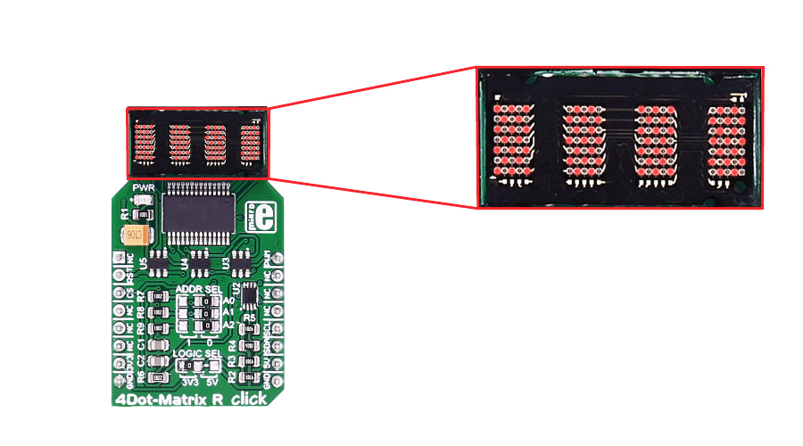
SLO2016 is a 4-Digit 5x7 Dot Matrix Alphanumeric intelligent display, with many built-in functions that will save your time. The integrated circuit contains memory, a 128 ASCII ROM decoder, multiplexing circuitry and drivers.
The character set consists of 128 special ASCII characters for English, German, Italian, Swedish, Danish, and Norwegian. So, you don't need to build a character set yourself.
You also have direct access to each digit independently and asynchronously.
Specifications
| Type | LED Matrix |
| Applications | 4 characters of 5x7 dots display to your device |
| On-board modules | SLO2016 5 x 7 dot matrix display, MCP23017 port expander |
| Key Features | Built-in Memory, Built-in Character Generator, Built-in Multiplex and LED Drive Circuitry, Superior ESD Immunity, readability up to eight feet (2.5m) |
| Key Benefits | 128 Special ASCII Characters for English, German, Italian, Swedish, Danish, and Norwegian. |
| Interface | I2C |
| Input Voltage | 3.3V or 5V |
| Click board size | M (42.9 x 25.4 mm) |
Pinout diagram
This table shows how the pinout on 4Dot-Matrix R click corresponds to the pinout on the mikroBUS™ socket (the latter shown in the two middle columns).
Jumpers and settings
| Designator | Name | Default Position | Default Option | Description |
|---|---|---|---|---|
| ADDR SEL | A0/A1/A2 | 0 | 0 | I2C slave address selection |
| LOG SEL | Interface power supply | 5V | Logic Level Voltage Selection 3V3/5V, left position 3V3, right position 5V |
4Dot-Matrix R click features a jumper for setting the voltage logic level. By default, it's soldered to a 5V position.
Programming
Code examples for 4Dot-Matrix R click, written for MikroElektronika hardware and compilers are available on Libstock.
Code snippet
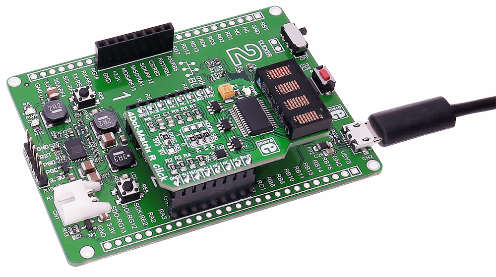
This code snippet demonstrates the usage of a 4DotMatrix R click on EasyMx PRO v7 for STM32 ARM with STM32F107VCT6 .
After the initialization, several pieces of text are displayed in a loop, showing the functionalities of the click board and its library. First, some text is slid in from the right. Next, a sequence of numbers is displayed in succession. Finally, the display is faded out and in using PWM.
01: ...
02:
03: // Main function.
04: void main()
05: {
06:     int8_t i;
07:     uint8_t length;
08:
09:     // Initialize the system.
10:     systemInit();
11:
12:     length = strlen(text) - 3;
13:     while (1)
14:     {
15:         // Slide some text in from the right.
16:         for (i = 0; i < length; i++)
17:         {
18:             C4DOT_writeText(text + i);
19:             Delay_ms(150);
20:         }
21:
22:         // Clear and delay.
23:         C4DOT_clearDisplay();
24:         Delay_ms(500);
25:
26:         // Write some numbers on the display.
27:         for (i = -20; i <= 20; i++)
28:         {
29:             C4DOT_writeIntDec(i);
30:             Delay_ms(150);
31:         }
32:
33:         // Clear and delay.
34:         C4DOT_clearDisplay();
35:         Delay_ms(500);
36:
37:         // Fade some text out and in.
38:         C4DOT_writeIntDec(1234);
39:         for (i = 50; i >= 0; i--)
40:         {
41:             PWM_TIM2_Set_Duty(
42:                 (pwmPeriod / 50) * i, _PWM_NON_INVERTED, _PWM_CHANNEL1);
43:             Delay_ms(50);
44:         }
45:         for (i = 0; i <= 50; i++)
46:         {
47:             PWM_TIM2_Set_Duty(
48:                 (pwmPeriod / 50) * i, _PWM_NON_INVERTED, _PWM_CHANNEL1);
49:             Delay_ms(50);
50:         }
51:
52:         // Clear and delay.
53:         C4DOT_clearDisplay();
54:         Delay_ms(500);
55:     }
56: }
Downloads
mikroBUS™ Standard specificationMCP23017 datasheet
SLO2016 datasheet
4Dot-Matrix R click schematic
Enter the code in the box below:


