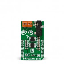
StereoAmp click
The StereoAmp click features a 3.5mm input jack and four output screw terminals for connecting passive speakers. It runs on either 3.3V or 5V power supply and communicates with the MCU through the I2C interface.

Volume control
Each LM48100Q-Q1 is used for one channel, left or right. Both input paths have their own independent, 32-step volume control.
The mixer, volume control and device mode select are controlled through an I2C compatible interface.
Bridge-tied load for more voltage
BTL or a bridge-tied load is an output configuration where the speakers are connected (bridged) between two audio amplifier outputs. In a single-ended configuration one side of the load is connected to the ground. Here both channels are connected, but one has an inverted signal. Compared to a single-ended configuration BTL has two times more voltage swing across the load (speakers).
The doubled voltage swing means four times more power to the speakers. This is ideal for applications and devices where due to battery size the supply voltage is lower.
Shutdown mode
The IC has an I2C selectable low power shutdown mode that disables the device, reducing current consumption to 0.01μA.
Output fault detection
The output fault detection system can sense load conditions and protect the device during short circuit events and detect open circuit conditions. The LM48100Q-Q1 output fault diagnostics are controlled through the I2C interface.
Specifications
| Type | Amplifier |
| Applications | Automotive audio devices, hands-free kits, battery operated devices, computers, MP3 players, etc. |
| On-board modules | LM48100Q-Q1 Boomer™ single supply, mono, bridge-tied load amplifier ICs by Texas Instruments |
| Key Features | Screw terminals for speaker output, Individual 32-step volume control |
| Key Benefits | Short circuit and thermal protection, Output fault detection |
| Interface | GPIO,I2C |
| Input Voltage | 3.3V or 5V |
| Compatibility | mikroBUS |
| Click board size | M (42.9 x 25.4 mm) |
Features and usage notes
StereoAmp click key features:
- Input Voltage Range –0.3 V to VDD = 0.3 V
- Output Power at VDD 1.3 W (at VDD = 5 V, RL = 8 Ω, THD+N ≤ 1%)
- Low power shut down mode 0.01 μA
- I2C Volume and Mode Control
- Input Mixer and Multiplexer
- Output fault detection
- Short circuit and thermal protection
- Individual 32-step volume control
- I2C interface
- 3.5mm input audio jack
- Screw terminals for speaker output
- Runs on either 3.3V or 5V power supply
Pinout diagram
This table shows how the pinout on StereoAmp click corresponds to the pinout on the mikroBUS™ socket.
Programming
The demo shows how to initialize amplifiers and set volume control registers on the fly. It uses joystick or potentiometer (depending on the development board) to control volume and TFT or LCD display to show gain level. Before initializing I2C module, the demo toggles SDA and SCL lines for proper initialization of amplifiers.
The following code enables amplifiers and selects input 1, sets volume to predefined value, and restores diagnostic register. Function Write_Amp_Reg writes to selected amplifier's register using I2C bus.
 1 void StereoAmp_Init() {
 2     // Power On and Input 1 enabled.
 3     Write_Amp_Reg(LEFT_SPEAKER, MODE_CONTROL_REG, POWER_ON | INPUT1);
 4     Write_Amp_Reg(RIGHT_SPEAKER, MODE_CONTROL_REG, POWER_ON | INPUT1);
 5     // Set volume.
 6     Write_Amp_Reg(LEFT_SPEAKER, VOLUME_CONTROL1_REG, volume_control_L);
 7     Write_Amp_Reg(RIGHT_SPEAKER, VOLUME_CONTROL1_REG, volume_control_R);
 8     // Restore diagnostic.
 9     Write_Amp_Reg(LEFT_SPEAKER, DIAGNOSTIC_CONTROL_REG, DG_RESET );
10     Write_Amp_Reg(RIGHT_SPEAKER, DIAGNOSTIC_CONTROL_REG, DG_RESET );
11 }
Downloads
mikroBUS™ Standard specificationEnter the code in the box below:


