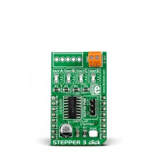
Stepper 3 click
The board carries a Texas Instruments ULN2003 High-Current Darlington transistor array for operating the motors.
Motors are connected through a 4-pin male connector on the top of the PCB. They can be driven by the click board's own power supply, or with an external power supply which can be brought through onboard screw terminals (up to 30V).
Stepper 3 click communicates with the target board MCU through mikroBUS™ PWM, AN, RST and CS pins (here used for individual motor phases, marked INA, INB, INC, IND).
The board is designed to use a 5V power supply only.
Specification
| Type | Stepper |
| Applications | Board step motors in full-, half-, quarter-, eighth- and sixteenth-step modes |
| On-board modules | Texas Instruments ULN2003 High-Current Darlington transistor array |
| Key Features | Connector for external power supply up to 30V |
| Key Benefits | Precise motor control: individual phases can be accessed separately |
| Interface | GPIO |
| Input Voltage | 5V,5V |
| Compatibility | mikroBUS |
| Click board size | M (42.9 x 25.4 mm) |
Stepper 3 click is for driving a unipolar stepper motor with precise controls (individual motor phases can be accessed separately).
Features and usage notes
An onboard jumper allows you to switch between the internal or external power supply.
Two other Stepper click boards are available, with slightly different characteristics. See Stepper click and Stepper 2 click for more information. The Libstock library encompasses all three boards. A detailed explanation of how to configure it is available on our Learn pages.
The Learn page also has an introduction to stepper motors.
Programming
This snippet sets up and runs the stepper motor at 30 steps per second.
 1 void main()
 2 {
 3     stepper_init( 0, 72, false, false, true );
 4     stepper_init_fp( forward, backward );
 5     stepper_set_max_speed( 30.0 );
 6     stepper_set_speed( 30.0 );
 7
 8     while( 1 )
 9     {
10        stepper_run_speed();
11     }
12 }
Code examples that demonstrate the usage of Stepper 3 click with MikroElektronika hardware, written for mikroC for ARM, AVR, dsPIC, FT90x, PIC and PIC32 are available on Libstock.
Downloads
Enter the code in the box below:


