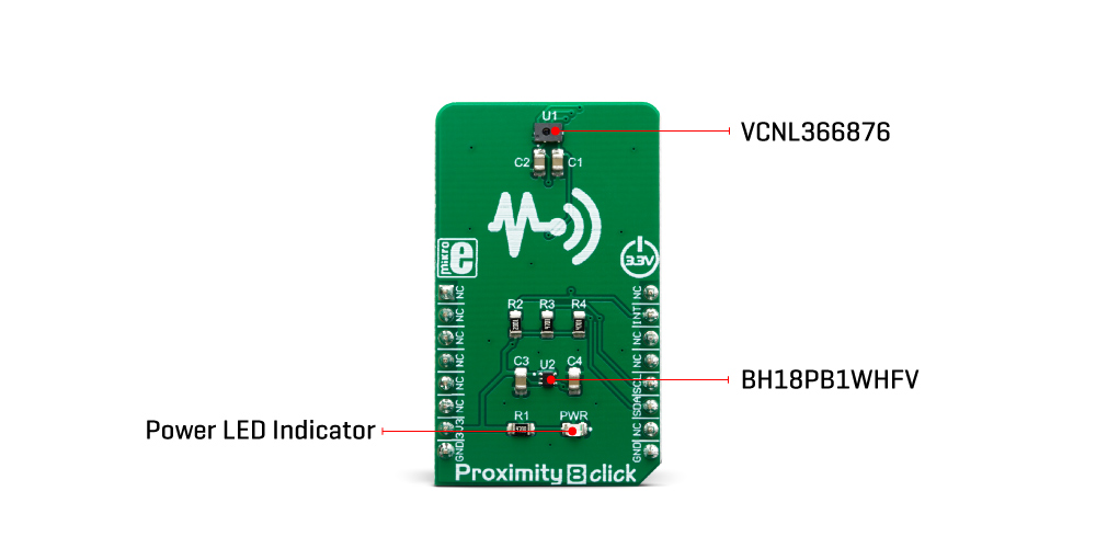
Proximity 8 click
The Click board™ can detect objects regardless of their color, thanks to the VCSEL that emits a light beam with the wavelength of 940nm. This makes it also immune to a red glow. The current through the VCSEL can be programmed by the user, allowing yet another aspect of controlling the power consumption, which is already about 10x less than other similar sensors. These features make Proximity 8 a perfect solution for the development of battery-operated and mobile applications, IoT applications, and similar applications that require low power consumption and reliable PS detection in close range.
How does it work?
Proximity 8 click is based around the VCNL36687S, a proximity sensor with VCSEL in a single package, with the I2C Interface, from Vishay. This is a proximity sensor aimed towards portable, mobile and IoT applications, where close proximity detection is required. A good example might be a display activation in the close proximity of an operator. The sensor itself has an advanced analog and digital frontend circuits, which make it easy working with the sensor: it can be set to trigger a PS detection by a single operation over the I2C. The rest of the time, it will stay in the standby mode, saving the power that way.

The VCNL36687S features a 12-bit ADC, therefore the output data is in 12-bit format. There are two registers that are used to hold the output result. Besides the four Most Significant Bits (MSBs), the PS data output high-byte register contains another bit that indicates that the device entered the sunlight protection mode.
The operation of the VCNL36687S can be configured by writing to a set of CONFIG registers. There are four config registers, which are used to set the PS sampling period, interrupt persistence value, smart persistence, interrupt, operating mode, etc. The comprehensive list of all the registers and their function is given within the VCNL36687S datasheet. However, Proximity 8 click supports a mikroSDK compatible library, which contains a set of functions used to simplify and accelerate the development.
There are two pairs of threshold registers, used to trigger an interrupt when the measurement exceeds their values. These registers contain two 12-bit values, which represent the boundaries of the detection window. Each time one of these values is exceeded, an interrupt will be generated, and the INT pin will be asserted to a LOW logic level. The interrupt flag bit indicates the condition that caused an interrupt. The interrupt persistence can be set, preventing false triggering: the INT pin will be asserted only after a number of consecutive measurements that exceed either of the threshold values. This pin is routed to the mikroBUS™ INT pin, and it is normally pulled up by a resistor.
Another feature of the VCNL36687S sensor is the Logic Output mode: close proximity of an object will trigger an interrupt (a logic LOW level on the INT pin). When the object moves away, the INT pin will be de-asserted (a logic HIGH level on the INT pin). The difference between this mode and the other modes is that the user does not have to read the status bit to clear the interrupt and de-assert the INT pin. It will be controlled automatically by the low/high threshold values.
To improve the reliability of the detection, the VCNL36687S employs a smart cancelation scheme. It uses the value stored within the register to subtract it from the output measurement, reducing the crosstalk phenomenon. A sunlight mode allows the device to be used even when exposed to sunlight.
The VCNL36687S is operated by 1.8V, therefore a voltage regulator IC had to be used. The logic section of the VCNL36687S allows it to be operated at 3.3V directly, so no logic level translation is required if the Click board™ is used with MCUs that use 3.3V logic levels. However, if operated by an MCU that uses 5V for logic levels, a proper logic level voltage translation is required.
Specifications
| Type | Proximity |
| Applications | It is a perfect solution for the development of battery-operated and mobile applications, IoT applications, and similar applications that require low power consumption and reliable PS detection in close range. |
| On-board modules | VCNL36687S, a proximity sensor with VCSEL in a single package, with the I2C Interface, from Vishay. |
| Key Features | Very low power consumption reached by using advanced analog and digital frontends. VCSEL onboard allows red glow immunity, intelligent crosstalk cancelation, fast PS response, programmable interrupt engine which allows extremely useful Logic Output mode, etc. |
| Interface | I2C |
| Input Voltage | 3.3V |
| Click board size | M (42.9 x 25.4 mm) |
Pinout Diagram
This table shows how the pinout on Proximity 8 click corresponds to the pinout on the mikroBUS™ socket (the latter shown in the two middle columns).
Onboard Settings And Indicators
| Label | Name | Default | Description |
|---|---|---|---|
| PWR | PWR | - | Power indication LED |
Software Support
We provide a library for the Proximity 8 click on our LibStock page, as well as a demo application (example), developed using MikroElektronika compilers. The demo can run on all the main MikroElektronika development boards.
Library Description
The library provides all the necessary functions for reading registers and writing data to the registers.
Key functions:
void proximity8_writeData(uint8_t reg, uint16_t dataIn)- Function for writing data into the register.uint16_t proximity8_readData(uint8_t reg)- Function for reads data from register.uint8_t proximity8_getInterruptState()- Get interrupt state on the INT pin.
Examples description
The application is composed of the three sections :
- System Initialization - Initializes I2C module and sets INT pin as INPUT.
- Application Initialization - Initialization Driver init, test comunication and configuration chip for measurement.
- Application Task - Reads Proximity data and this data logs to the USBUART every 1500ms.
Note: The reading value and proximity of the data depend on the configuration.
void applicationTask()
{
   uint16_t Proximity;
   char demoText[ 50 ] = {0};

   Proximity = proximity8_readData(_PROXIMITY8_REG_PROX_DATA);
   Proximity = (Proximity & 0x7FFF);

   IntToStr(Proximity, demoText);
   mikrobus_logWrite(" Proximity data: ", _LOG_TEXT);
   mikrobus_logWrite(demoText, _LOG_LINE);

   mikrobus_logWrite("-------------------------", _LOG_LINE);
   Delay_ms( 1500 );
}
The full application code, and ready to use projects can be found on our LibStock page.
Other mikroE Libraries used in the example:
I2CUARTConversions
Additional notes and informations
Depending on the development board you are using, you may need USB UART click, USB UART 2 click or RS232 click to connect to your PC, for development systems with no UART to USB interface available on the board. The terminal available in all MikroElektronika compilers, or any other terminal application of your choice, can be used to read the message.
MIKROSDK
This click board is supported with mikroSDK - MikroElektronika Software Development Kit. To ensure proper operation of mikroSDK compliant click board demo applications, mikroSDK should be downloaded from the LibStock and installed for the compiler you are using.
For more information about mikroSDK, visit the official page.
Downloads
mikroBUS™ Standard specification
Enter the code in the box below:


