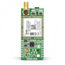
GSM Click
Precision control
GSM click is the easiest way to add GSM/GPRS communication to your device. The click features Telit's GL865-QUAD module. GSM click runs either on 3.3V or 5V power supply and communicates with the target microcontroller via UART interface.
Python Script Interpreter
It is possible to run an application from inside the module via the embedded Python Script Interpreter. Python is an easy-to-use programming language with clear syntax, and an interface that makes it simple to test small snippets of code.
Quad-band coverage
The module has worldwide coverage - 850/900/1800/1900 MHz frequencies. GSM supports incoming and outgoing voice calls, sms and data communication (via GPRS)
Power saving modes
In power saving mode, the GL865-QUAD uses around 1.5 mA, and in power off mode it uses less than 5 μA. That is considerably low and ideal for IoT devices that rely on long battery life and low power consumption.
Phonebook
The Phonebook function allows storing of telephone numbers in the SIM memory. The capability of the Phonebook depends on the SIM version and its embedded memory. The SIM card socket is located at the back side of the click board.
Additional information about the GSM click
GSM click contains TXB0106 6-bit bidirectional voltage-level translator, for interfacing components that operate on different voltages from one another.
On-board SMA antenna connector as well as 3.5mm quadrupole earphone/microphone jack.
An onboard jumper (J1) is used to switch between 3.3V and 5V I/O voltage levels; by default, it's soldered in the 3.3V position.
Applications
Remote monitoring automation, asset tracking, surveillance and security, home automation systems, point of sales terminals etc.
Specification
| Type | GSM |
| Applications | GSM click with it’s Telit GL865-QUAD IC is ideal for mobile devices. |
| On-board modules | Telit GL865-QUAD GSM/GPRS |
| Key Features | On-board antenna connector as well as 3.5mm quadrupole earphone/microphone jack. SIM card socket integrated at the bottom side of the board. |
| Key Benefits | Supports GSM/GPRS 850/900/1800/ 1900 MHz Quad-band frequency. Supports GSM/GPRS protocol stack 3GPP. |
| Interface | GPIO,UART |
| Input Voltage | 3.3V or 5V |
| Compatibility | mikroBUS |
| Click board size | L (57.15 x 25.4 mm) |
Key features
- GL865-QUAD from Telit
- Quad-band GSM | GPRS 850 / 900 / 1800 / 1900 MHz
- TCP/IP protocol stack
- integrated 3GPP protocol stack
- Power consumption in power off mode: 5μA
- Sensitivity:
- 108 dBm (typ.) @ 850/900 MHz
- 107 dBm (typ.) @ 1800/1900 MHz
- TXB0106 voltage-level translator
- Phyton Script Interpreter
- Interface: RX, TX, INT, PWM, CS, RST and AN pin
- Either 3.3V or 5V power supply
Downloads
Alternative GSM Libstock Library
GSM click Cross-Platform Guide
Pinout diagram
This table shows how the pinout on GSM click corresponds to the pinout on the mikroBUS™ socket (the latter shown in the two middle columns).
Programming
The following code snippet shows how the GSM engine is initialized. The function calls the initialization of AT adapter, timer and parser. This should be done before executing any other function.
 1 void GSM_init( void )
 2 {
 3     engine_init( gsm_default_handler );
 4     hal_gsm_pwr( 0 );
 5     Delay_ms( 100 );
 6     hal_gsm_pwr( 1 );
 7     Delay_ms( 2500 );
 8     hal_gsm_pwr( 0 );
 9
10     at_cmd( "AT" );
11     at_cmd( "AT+CSCS="GSM"" );
12     at_cmd( "AT+CMGF=1" );
13 }
Enter the code in the box below:


