Current 2 Click
Current 2 click features a very low error margin of less than 0.2%, a very low offset and quiescent current, allowing the voltage across the sense resistor as high as 2.5V. The output current is converted to voltage and fed to the 10-bit A/D converter, which uses a voltage reference IC, for improved accuracy. Thanks to the external sense resistor, Current 2 click is able to provide readings for quite a large current through the connected load. Due to the high-side sensing configuration, Current 2 click does not disturb the GND potential of the connected load and allows the detection of the short-circuit condition at the input. The A/D converter allows reading the measured current via the SPI interface.
How does it work
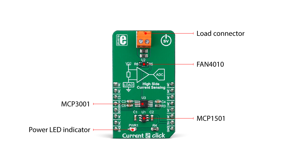
The Current click 2 is based on the FAN4010, a high-side current sensor by ON Semiconductor (formerly Fairchild). This integrated circuit is a transimpedance amplifier suitable for the current sensing through the shunt resistor on the high side, between the power supply and the connected load. This allows the short circuit on the load to be sensed and will not disturb the GND reference of the connected load since the shunt resistor between the load negative connection terminal and the GND is avoided. These advantages are especially useful for battery charging applications and battery gauges since the short circuit detection is very important in such applications. Also, the negative terminal of the battery has to stay on the same potential as the GND for the temperature output to be accurate, which is impossible with the low-side shunt resistor.

The similar schematic could be designed using only operational amplifiers, however due to a high inaccuracy of such design (as the offset voltage of a typical operational amplifier can greatly affect the output current, especially after the amplification is applied), and the low common mode voltage that typical operational amplifier can withstand, specialized current sensing amplifier ICs (CSA) such as the FAN4010, are used instead.
The FAN4010 features an extremely low current offset of only 2 µA, which allows very accurate measurement within the 0.2% margin. The transconductance ratio at the output of the FAN4010 is 10 mA/V, where V represents the voltage across the shunt resistor. The current at the output linearly depends on the current through the load. By using the appropriate resistor between the output and the GND, this current can be scaled to an appropriate voltage level that can be used as the input for the A/D converter.
The MCP3001, a 10-bit A/D converter (ADC) with SPI interface, from Microchip. It is a high-performance, low-noise single-supply ADC, which can deliver up to 200,000 samples per second (200 ksps). This makes it well suited for fast monitoring applications. It is also equipped with the reference input pin, allowing it to use an accurate voltage reference, which ensures very high sampling accuracy. Combined with the MCP1501-20 IC, a high-precision, buffered voltage reference of 2.048V, it is used with enough headroom to sample load current up to 4 A (4 A = 2 V at the ADC input).
The calculation formulas can derived from the datasheet of the FAN4010. However, it is not necessary to perform any calculations if using mikroSDK compatible functions, provided for this Click board™. These functions already contain all the necessary calculations and output the current through the connected load directly in physical units [mA]. The included example demonstrates their practical usage.
Specifications
| Type | Current sensor |
| Applications | This Click board™ is a perfect solution for the battery charging monitoring, various battery gauges, and other similar low voltage applications that require simple and reliable current monitoring. |
| On-board modules | FAN4010, a high-side current sensor by ON Semiconductor (formerly Fairchild); MCP3001, a 10-bit A/D converter (ADC) with SPI interface; MCP1501-20 IC, a high-precision, buffered voltage reference of 2.048V, both from Microchip. |
| Key Features | A very low series resistance, high-side sensing approach with no shunt resistor that disturbs the GND reference, highly accurate 10-bit A/D converter, combined with the precise voltage reference source.e |
| Interface | SPI |
| Input Voltage | 5V |
Pinout diagram
This table shows how the pinout on Current 2 Click corresponds to the pinout on the mikroBUS™ socket (the latter shown in the two middle columns).
Onboard settings and indicators
| Label | Name | Default | Description |
|---|---|---|---|
| LD1 | PWR | - | Power LED indicator |
| TB1 | - | - | Load connector |
Software support
We provide a library for the Current 2 Click on our LibStock page, as well as a demo application (example), developed using MikroElektronika compilers. The demo can run on all the main MikroElektronika development boards.
Library Description
Library offers a choice to get 10bit result from the AD converter as one sample result or averaged result with desired number of samples. Result from the ADC can be calculated to get current in a proper value [mA], depending on the RSENSE, ROUT and VREF on the Current 2 Click board. For more details check documentation.
Key functions:
uint16_t current2_getADC( void )- Function returns 10-bit digital value from the AD converter.uint16_t current2_getAverageADC( uint8_t nSamp )- Function returns averaged result from the AD converter.uint16_t current2_getCurrent( uint8_t nSample )- Function reads averaged result from the ADC and performs a calculations to get current in proper value [mA].
Examples description
The application is composed of the three sections :
- System Initialization - Initializes peripherals and pins.
- Application Initialization - Initializes SPI interface in Mode 0.
- Application Task - (code snippet) - Reads the current averaged result of 20 samples and gets this result in a proper value [mA]. Repeats the current reading every 500ms.
void applicationTask()
{
    current = current2_getCurrent( 20 );

    WordToStr( current, text );

    mikrobus_logWrite( "Current : ", _LOG_TEXT );
    mikrobus_logWrite( text, _LOG_TEXT );
    mikrobus_logWrite( " mA", _LOG_LINE );

    Delay_ms( 500 );

}
The full application code, and ready to use projects can be found on our LibStock page.
Other mikroE Libraries used in the example:
ConversionsSPIUART
Additional notes and information
Depending on the development board you are using, you may need USB UART click, USB UART 2 click or RS232 click to connect to your PC, for development systems with no UART to USB interface available on the board. The terminal available in all MikroElektronika compilers, or any other terminal application of your choice, can be used to read the message.
mikroSDK
This click board is supported with mikroSDK - MikroElektronika Software Development Kit. To ensure proper operation of mikroSDK compliant click board demo applications, mikroSDK should be downloaded from the LibStock and installed for the compiler you are using.
For more information about mikroSDK, visit the official page.
Downloads
mikroBUS™ Standard specificationEnter the code in the box below:


-80x80.jpg)

