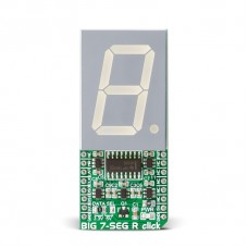
BIG 7-SEG R click
BIG 7-SEG R click is what you need if you want to add a seven-segment LED display to your project. This click features an SC10-21SRWA seven-segment display. Communication between the MCU and the SC10-21SRWA display is established via serial-IN, parallel-OUT shift register 74HC595 IC.
The click runs on either 3.3V of 5V power supply and communicates with the target MCU over an SPI interface.
Display
The click displays letters, numbers and symbols in highly readable form. It can be used in any simple interface and combined with other click boards. The color of the displayed character is red, as the R in the name of the click states.
Light intensity
The light intensity on the display is controlled via the PWM pin on the board.
Applications
Adding a seven-segment LED display to your device with SPI interface.
Specifications
| Type | LED Segment |
| Applications | Adding a seven-segment LED display to your device with SPI interface |
| On-board modules | SC10-21SRWA seven-segment display, parallel-OUT shift register 74HC595 IC |
| Key Features | 1.0 inch digit height, Standard: grey face, white segment, Low current operation |
| Key Benefits | Letters, numbers and symbols in highly readable form |
| Interface | SPI,PWM,GPIO |
| Input Voltage | 3.3V or 5V |
| Compatibility | mikroBUS |
| Click board size | L (57.15 x 25.4 mm) |
Pinout diagram
This table shows how the pinout on BIG 7-SEG R click corresponds to the pinout on the mikroBUS™ socket (the latter shown in the two middle columns).
Jumpers and settings
Information about onboard jumpers:
| Designator | Name | Default Position | Default Option | Description: describe the use + list all options with respective descriptions |
|---|---|---|---|---|
| JP1 | Logic level | Left | 3.3V | Logic Level Selection toward host mcu 3.3V/5V, left position 3.3V, right position 5V |
Programming
This demo is using BIG 7-SEG R click board to display characters in an endless loop, with fixed time interval whilst changing its PWM duty.
- Operating Voltage Range: 2.0 to 6.0 V
- Operating Temperature: – 55 to 125 C
This example for STM32F107VC MCU ( EasyMx PRO v7 for ARM ), resets and initializes the BIG 7-SEG R click board takes characters from the static array and displays them while changing PWM duty cycle, all in an endless loop.
 1   extern char dig_array[MAX_CHARACTERS];
 2
 3   // Variables
 4   unsigned short counter;
 5   unsigned int luminosity;
 6   unsigned int pwm_period;
 7   int8_t valid;
 8
 9   char demo_array[20] =
10   { 'M', 'I', 'K', 'R', 'O',
11     'E', 'L', 'E', 'K', 'T', 'R', 'O', 'N', 'I', 'K', 'A',
12     '2', '0', '1', '6'
13   };
14
15   void main()
16   {
17    // MCU Init
18    GPIO_Digital_Output(&GPIOD_ODR, _GPIO_PINMASK_13);     // Set PORTD.B13 as digital input
19    GPIO_Digital_Output(&GPIOC_ODR, _GPIO_PINMASK_2);      // Set PORTC.B2 as digital output
20
21    // SPI Init
22    SPI3_Init_Advanced( _SPI_FPCLK_DIV16, _SPI_MASTER | _SPI_8_BIT |
23   _SPI_CLK_IDLE_LOW | _SPI_FIRST_CLK_EDGE_TRANSITION |
24   _SPI_MSB_FIRST | _SPI_SS_DISABLE | _SPI_SSM_ENABLE |
25   _SPI_SSI_1, &_GPIO_MODULE_SPI3_PC10_11_12 );
26
27    // PWM Init
28    pwm_period = PWM_TIM5_Init(5000);                      // PWM Init on 5kHz
29    PWM_TIM5_Set_Duty(100, _PWM_NON_INVERTED, _PWM_CHANNEL1);
30    PWM_TIM5_Start(_PWM_CHANNEL1, &_GPIO_MODULE_TIM5_CH1_PA0);
31
32    // 74HC595 Init
33    HC595_LAT = 0;
34    HC595_RES = 0;
35    HC595_reset();
36
37    // Init counter and segment luminosity
38    counter = 0;
39    luminosity = 0;
40
41    // Endless loop
42    while (1)
43     {
44      valid = seg_7_display(demo_array[counter]);
45      PWM_TIM5_Set_Duty(100 + luminosity, _PWM_NON_INVERTED, _PWM_CHANNEL1);
46      delay_ms(750);
47      luminosity += 100;
48      counter++;
49      if (counter == 20)
50        counter = 0;
51      if (luminosity == 4000)
52        luminosity = 0;
53     }
54   }
Downloads
mikroBUS™ Standard specificationEnter the code in the box below:


