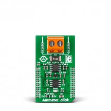
Ammeter click
Two onboard screw terminals (probe+ and probe-) are bringing in the current, which then passes through a shunt resistor. A voltage proportional to the strength of the current is generated accross the resistor. This voltage passes through an amplifier before it's fed into a 12-bit ADC which then outputs a digital value through the mikroBUS SPI interface.
The firmware processes the digital value to determine the exact amperage between 1mA and 1A for DC current. It's also possible to measure AC current by deriving the value from peak to peak measurements. At the same time, the voltage can be directly monitored through the AN pin.
The board uses either a 3.3V or 5V power supply (it's important not to power the board from the same power source you wish to measure).
Specification
| Type | Measurements |
| Applications | Electric current measuring and monitoring |
| On-board modules | MCP3201 ADC, MAX6106, AD8616 OpAmp |
| Key Features | Maximum voltage for safe use: 48 V |
| Key Benefits | Measures both DC and AC, 0.1A - 1A measurement range |
| Interface | Analog,SPI |
| Input Voltage | 3.3V or 5V |
| Compatibility | mikroBUS |
| Click board size | M (42.9 x 25.4 mm) |
Ammeter click is a mikroBUS™ add-on board with circuitry for measuring electric current (both AC and DC).
Features and usage notes
Two onboard screw terminals (probe+ and probe-) are bringing in the current, which then passes through a shunt resistor. A voltage proportional to the strength of the current is generated accross the resistor. This voltage passes through an AD8615 operational amplifier before it's fed into a 12-bit ADC which then outputs a digital value through the mikroBUS™ SPI interface. Ammeter click carries MCP3201, a 12-bit ADC. In case you need more precise measurements with a higher sample rate, you can use Ammeter click with a DSP microcontroller. In such case you would take the analog voltage directly through the click's AN pin. In both cases, the firmware processes the digital value to determine the exact amperage between 1mA and 1A for DC current. It's also possible to measure AC current by deriving the value from peak to peak measurements. At the same time, the voltage can be directly monitored through the AN pin. The maximum safe voltage range for the current measured is 48V. The board uses either a 3.3V or 5V power supply (it's important not to power the board from the same power source you wish to measure).
Programming
This code snippet shows how to read the ADC values from the board.
 1 unsigned int getADC()
 2 {
 3     char i, buffer;
 4     volatile unsigned int read, read1, avrg, sum;
 5     sum = 0;
 6     for(i=0; i<10; i++ )
 7     {
 8         Chip_Select = 0;
 9         read = SPI1_Read(buffer);
10         read1 = SPI1_Read(buffer);
11         Chip_Select = 1;
12         read = ((read & 0x1F) << 8);
13         read = ((read | read1) >> 1);
14         sum = sum + read;
15     }
16
17     avrg = sum / 10;
18     return avrg;
19 }
Code examples that demonstrate the usage of Ammeter click with MikroElektronika hardware, written for mikroC for PIC are available on Libstock
Downloads
Enter the code in the box below:


