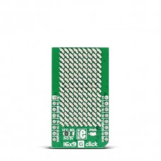
16x9 G click
16x9 G click contains a green LED matrix and the IS31FL3731 audio modulated matrix LED driver. The dimension of the LED matrix is 16x9. Each LED can be controlled individually – both for on/off control and light intensity. The click is designed to run on either 3.3V or 5V power supply. It communicates with the target microcontroller over I2C interface and the following mikroBUS™ pins: PWM, INT, CS.
The IS31FL3731 matrix driver
The IS31FL3731 is a compact LED driver for 144 single LEDs. The driver has three operating modes, Picture Mode, Auto Frame Play Mode and Audio Frame Play Mode:
Picture Mode — the driver can store up to 8 frames. In Picture Mode you can show one of these frames at a time.
Auto Frame Play Mode — In this mode you can automatically play the 8 frames in order.
Audio Frame Play Mode —You can play the 8 frames to the rhythm of the music of your choice. The displayed LED frames can be modulated with audio signal intensity. The driver plays the first frame when the value is the smallest and plays the eighth frame when the value is the biggest.
For more information about the different modes, see the LED driver datasheet.
Audio signal - The LED frames can be modulated with the intensity of the audio signal.
Light intensity - It is possible to set the intensity of each frame individually, and to use the intensity setting of frame 1 for all other frames.
Specifications
| Type | LED Matrix |
| Applications | LED display for various hand-held devices, home appliances, IoT devices, etc. |
| On-board modules | IS31FL3731 matrix LED driver |
| Key Features | 16x9 LED matrix, 144 single LEDs, 8 frames memory for animations, Individual blink control, Auto Frame Play Mode, Audio Frame Play Mode |
| Key Benefits | light intensity control, Audio Frame Play Mode |
| Interface | GPIO,I2C |
| Input Voltage | 3.3V or 5V |
| Compatibility | mikroBUS |
| Click board size | M (42.9 x 25.4 mm) |
Pinout diagram
This table shows how the pinout on 16x9 G click corresponds to the pinout on the mikroBUS™ socket (the latter shown in the two middle columns).
Jumper and Settings
This table shows the onboard jumpers and additional settings.
| Designator | Name | Default Position | Default Option | Description |
|---|---|---|---|---|
| JP1 | PWR.SEL. | Left | 3V3 | Power Supply Voltage Selection 3.3V/5V, left position 3.3V, right position 5V |
| JP2 | ADDR SEL | Left | 0 | The last two bits of the I2C address |
Programming
The Library provide access to the function registers of the driver, and basic graphic manipulation of each frame.
Code snippet
The code snippet shows how to draw one frame and display it.
01 void main()
02 {
03     system_init();
04
05     // Hardware power on.
06     click_16x9_shutdown_hw(false);
07     // Software shutdown mode.
08     click_16x9_shutdown_sw(true);
09
10     // Turn on all LED's in frame 1, and draw circle.
11     click_16x9_begin_frame(FRAME_1);
12     {
13         click_16x9_control_all(CTRL_LED, true);
14         click_16x9_fill_screen(0x00);
15         click_16x9_circle(x, y, radius, pwm);
16     }
17     click_16x9_end_frame();
18
19     // Display frame 1.
20     click_16x9_func_reg(REG_PICTURE_DISPLAY, 0);
21
22     // Software normal operation mode.
23     click_16x9_shutdown_sw(false);
24
25     while (1);
26 }
Downloads
mikroBUS™ Standard specification16x9 G click Schematic
LibStock: 16x9 G click Examples
Enter the code in the box below:


