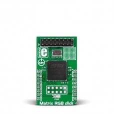
Matrix RGB click
Matrix RGB click is a mikroBUS™ add-on board powered by a 32-bit FT900 MCU designed specifically for powering 16x32 RGB LED matrices. The board has a 16 wire IDC connector for connecting to a single 16x32 LED panel; however, the firmware inside the FT900x chip can drive more than one panel. Multiple panels can be connected to each other into a daisy-chain configuration (see the video). Matrix RGB click communicates with the target MCU through the SPI interface. It uses a 3.3V power supply only. Complete kits with Matrix RGB click, a single 32x32 RGB LED matrix panel (consisting of two 16x32 matrices joined together), and a power supply unit are available to order.
Alternatively, panels and power supplies can be purchased separately.
Specification
| Type | LED Matrix |
| Applications | Driving up to 16 16x32 RGB LED panels (more than 32 is possible, but flickering may occurr) |
| On-board modules | 32-bit FT900 MCU |
| Key Features | Can drive up to 16 panels of 16x32 RGB LEDs, Removes the load from the host MCU |
| Key Benefits | Custom firmware simplifies integration, Able to drive multiple panels chained together, Microcontroller can be accessed through separate IDC connector |
| Interface | GPIO,SPI |
| Input Voltage | 3.3V |
| Compatibility | mikroBUS |
| Click board size | M (42.9 x 25.4 mm) |
Features and usage notes
RGB Panels are driven by shift registers. There are 9 shift registers for driving LED colors and row selections effectively, along with 3 pins to latch, clock and enable leds. There are 2 for each color, 3 for row selection( A, B, C ), clock pin ( CLK ), latch pin ( STB ), and a OE / enable pin. Top row color shift registers are labeled R1, G1 and B1, while bottom row color registers are labeled R2, G2 and B2. Row selection registers are used to make re-writes appear more fluent. While your row selection is set to row 0, row 8 will also be updated. Shifting data onto R1, B1 and G1, will update row 0 data, and R2, B2, and G2 will update row 8.
Multiple panels can be connected to each other into a daisy-chain configuration (see the video). Matrix RGB click communicates with the target MCU through the SPI interface. It uses a 3.3V power supply only.
A detailed development guide is available on the learn page.
However powerful, Matrix RGB click is only a driver board, and you need to have one or more RGB panels and a power adapter to see the output. Make sure to buy them along with the click.
A full Matrix RGB development kit is also available. It includes matrix RGB click, 32x32 RGB LED Matrix Panel - 6mm pitch, 12V-3A power supply with EU plug (can power up up to two panels)
Programming
This snippet shows how to initialize the matrix, add scrolling text, scroll bitmap images, all with different colors and speeds very easily.
1 #include "matrixrgb_hw.h"
2 #include "resources.h"
3
4 sbit MATRIXRGB_CS at GPIOD_ODR.B13;
5 sbit MATRIXRGB_READY at GPIOD_IDR.B10;
6 sbit MATRIXRGB_RST at GPIOC_ODR.B2;
7
8 void system_setup( uint8_t width, uint8_t height );
9
10 void main()
11 {
12 color_t my_color;
13
14 system_setup( 2, 1 );
15
16 matrixrgb_scroll_img_left( MikroE_Sign_bmp, 32, 32, 4 );
17 matrixrgb_scroll_off_scrn_down( 4 );
18 matrixrgb_set_color( &my_color, 1, 1, 1 );
19 matrixrgb_scroll_text_right( "Matrix ", my_color, 10, 10 );
20 matrixrgb_set_color( &my_color, 1, 0, 0 );
21 matrixrgb_scroll_text_left( "R", my_color, 10, 1 );
22 matrixrgb_set_color( &my_color, 0, 1, 0 );
23 matrixrgb_scroll_text_left( "G", my_color, 10, 1 );
24 matrixrgb_set_color( &my_color, 0, 0, 1 );
25 matrixrgb_scroll_text_left( "B ", my_color, 10, 1 );
26 matrixrgb_set_color( &my_color, 1, 1, 1 );
27 matrixrgb_scroll_off_scrn_up( 10 );
28 matrixrgb_set_color( &my_color, 1, 0, 0 );
29 matrixrgb_scroll_img_right( MikroeBITMAP_bmp, 64, 16, 10 );
30 matrixrgb_scroll_off_scrn_right( 10 );
31 matrixrgb_set_color( &my_color, 1, 0, 0 );
32 matrixrgb_image_load( MikroeBITMAP_bmp, 64, 16 );
33 matrixrgb_scroll_img_right( MikroeBITMAP_bmp, 64, 16, 10 );
34 while(1)
35 {
36 matrixrgb_scroll_text_left( "MikroElektronika", my_color, 3, 16 );
37 matrixrgb_set_color( &my_color, 1, 1, 1 );
38 matrixrgb_scroll_text_left( "Matrix", my_color, 20, 10 );
39 matrixrgb_set_color( &my_color, 1, 0, 0 );
40 matrixrgb_scroll_text_left( "R", my_color, 20, 1 );
41 matrixrgb_set_color( &my_color, 0, 1, 0 );
42 matrixrgb_scroll_text_left( "G", my_color, 20, 1 );
43 matrixrgb_set_color( &my_color, 0, 0, 1 );
44 matrixrgb_scroll_text_left( "B", my_color, 20, 1 );
45
46 }
47 }
48
49 void system_setup( uint8_t width, uint8_t height )
50 {
51
52 GPIO_Digital_Output( &GPIOD_BASE, _GPIO_PINMASK_13); // Set Chip Select pin as output
53 GPIO_Digital_Output( &GPIOC_BASE, _GPIO_PINMASK_2 ); // Set Reset pin to output
54 GPIO_Digital_Input( &GPIOD_BASE, _GPIO_PINMASK_10); // Set Ready to input
55
56 // Initialize SPI
57 SPI3_Init_Advanced(_SPI_FPCLK_DIV2, _SPI_MASTER | _SPI_8_BIT |
58 _SPI_CLK_IDLE_LOW | _SPI_FIRST_CLK_EDGE_TRANSITION |
59 _SPI_MSB_FIRST | _SPI_SS_DISABLE | _SPI_SSM_DISABLE | _SPI_SSI_1,
60 &_GPIO_MODULE_SPI3_PC10_11_12);
61
62 MATRIXRGB_RST = 0; //Reset slave ( toggle )
63 Delay_ms(20);
64 MATRIXRGB_RST = 1;
65 Delay_ms(200);
66
67 matrixrgb_init( width, height );
68 Delay_ms(200);
69
70 }
Code examples that demonstrate the usage of Matrix RGB click with MikroElektronika hardware, written for mikroC for ARM, AVR, dsPIC, FT90x, PIC and PIC32 are available on Libstock.
Downloads
Learn Article - Matrix RGB Panel
Learn article: 2x2 panel with Matrix RGB click
Enter the code in the box below:


