Magneto 5 click
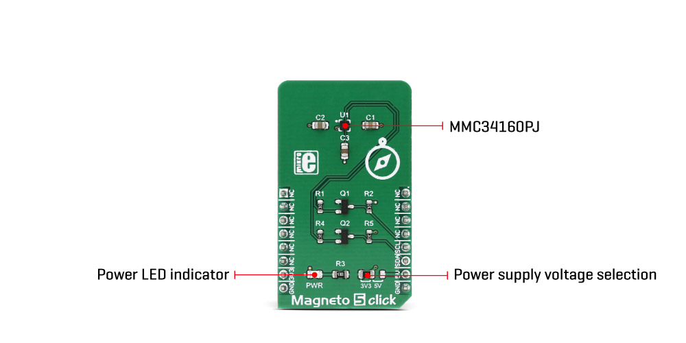
Magneto 5 click is a very accurate and reliable magnetic sensor device, which features the MEMSIC MMC34160PJ, a 3-axis magnetic sensor IC. MMC34160PJ IC features an onboard signal processing and I2C communication, simplifying the application development and reducing the host MCU load. It is a very accurate sensor, which can sense the heading direction with the precision of ±1˚, with the full-scale magnetic field detection of ±16 G. The device also has a RESET function, which eliminates measurement offset errors and restores the internal magnetic field orientation.
Featuring onboard signal processing, fast I2C communication, RESET function which restores the sensor accuracy, low power consumption, and high precision with the low noise, this Click board™ is an ideal solution for developing portable electronic compass applications, but it is not limited only to directional measurement. It can be also used for the detection of a magnetic field, vehicle detection, and similar applications that rely on an accurate magnetic field sensing in all three axes.
How does it work?
This Click board™ uses the MMC34160PJ, a 3-axis magnetic sensor IC from MEMSIC Inc. This integrated anisotropic magneto-resistive (AMR) sensor consists of permalloy film, deposited on a silicon wafer. One of the important characteristics of the permalloy (a nickel-iron alloy) is that it can be easily magnetized and demagnetized under the influence of the magnetic field. A strong field is applied during the manufacture, so that the permalloy film becomes magnetized, with the magnetic vector established in a specific direction. When the sensor is affected by an external magnetic field applied perpendicularly to the existing magnetic vector, it will rotate this vector and change its orientation. This will result in a change of the resistance of the permalloy, which varies with the intensity of the applied field. The MEMSIC AMR sensor is incorporated into a Wheatstone bridge configuration to maximize Signal to Noise ratio. This way, the influence of the external field can be measured.

The resulting characteristics of this sensor IC, are impressive: it can sense the heading direction with the accuracy of ±1˚, it has a high SNR with only 1.5 mG of total RMS noise, a resolution of ±0.5 mG when using 16 bit ADC mode, and ±16 G full-scale reading.
There are two internal configuration registers, used to set up the device and its working parameters. They allow the sampling resolution to be set (12bit, 14bit, or 16bit), sampling mode (continuous or single shot), the sampling frequency when working in continuous mode, and more. Among other options, these control registers offer a way to trigger SET and RESET event. Before SET or RESET pulses are triggered, an external capacitor connected to the CAP pin has to be recharged. This is also done by setting an appropriate bit in the control register.
The Status register offers the status indication for various events. It signalizes whether the integrated charge pump completed external capacitor recharging process, or if the reading of the internal register was successful, if the measurement was completed successfully, and it indicates the result of the self-test command.
The complete description of the internal registers can be found in the datasheet of the MMC34160PJ sensor IC. However, the included software library offers functions that simplify working with this device, taking care of the proper order of actions that needs to be followed, before reading the X, Y and Z position from the appropriate output registers. It also simplifies the reading process itself, providing the measurement values, directly.
To overcome situations where the external field might be too strong (more than 25 G) and disturb the internal magnetic vector of the permalloy film, a SET/RESET function is employed to restore the magnetic vector, by applying a high current pulse to an internal magnetically coupled strap.
The MMC34160PJ uses I2C communication, with the appropriate pins routed to the mikroBUS™. This ensures a reliable operation of the device. In addition, this device uses an SMD jumper, used to select the logic voltage level, allowing interfacing to both 3.3V and 5V MCUs. Two level shifting MOSFETs are used on I2C lines to allow both 3.3V and 5V operation since the sensor IC itself is not 5V tolerant.
Specifications
| Type | Magnetometer |
| Applications | It is an ideal solution for developing portable electronic compass applications, but it can be also used for the detection of a magnetic field, vehicle detection, and similar applications that rely on an accurate magnetic field sensing in all three axes. |
| Key Features | Accurate sensing of the magnetic field in all three axes, SET and RESET functions for the internal magnetic field restoration, on-chip processing functions, can be interfaced with the wide range of both 3.3V and 5V MCUs |
| Interface | I2C |
| Input Voltage | 3.3V,5V |
| Click board size | M (42.9 x 25.4 mm) |
Pinout diagram
This table shows how the pinout on Magneto 5 click corresponds to the pinout on the mikroBUS™ socket (the latter shown in the two middle columns).
Onboard settings and indicators
| Label | Name | Default | Description |
|---|---|---|---|
| LD1 | PWR | - | Power LED indicator |
| JP1 | 3V3, 5V | Left | Logic voltage level selection: left position 3.3V, right position 5V |
Magneto 5 click electrical specifications
| Description | Min | Typ | Max | Unit |
|---|---|---|---|---|
| Magnetic field measurement range on each axis | -16 | - | 16 | G |
| External disturbing field intensity | -25 | - | 25 | G |
| Heading accuracy | -1 | - | 1 | Deg (˚) |
Software support
We provide a library for Magneto 5 click on our Libstock page, as well as a demo application (example), developed using MikroElektronika compilers and mikroSDK. The provided click library is mikroSDK standard compliant. The demo application can run on all the main MikroElektronika development boards.
Library Description
This library provides generic functions for working with the Click board™.
Key functions:
void magneto5_reset( void );- Used to software reset the sensor.float magneto5_getAxisValue(uint8_t axis, uint8_t maxResolution);- The function returns the calculated Gauss value.void magneto5_getAxisData( int16_t *axisBuffer, uint8_t maxResolution );- Used for the reading of the raw axis data from registers.
Examples Description
The application is composed of three sections:
- System Initialization - Initializes I2C module
- Application Initialization - Initializes driver init and set measurement mode and channel
- Application Task - (code snippet) - Reads X / Y / Z data axis and logs to USBUART every 1 sec.
void applicationTask()
{
 X_axis = magneto5_getAxisValue( _MAGNETO5_AXIS_X, _MAGNETO5_CH3_12bits_1ms);
 Y_axis = magneto5_getAxisValue( _MAGNETO5_AXIS_Y, _MAGNETO5_CH3_12bits_1ms );
 Z_axis = magneto5_getAxisValue( _MAGNETO5_AXIS_Z, _MAGNETO5_CH3_12bits_1ms );

 FloatToStr( X_axis, writeText );
 mikrobus_logWrite( "-- X axis : ", _LOG_TEXT );
 mikrobus_logWrite( writeText, _LOG_LINE );

 FloatToStr( Y_axis, writeText );
 mikrobus_logWrite( "-- Y axis : ", _LOG_TEXT );
 mikrobus_logWrite( writeText, _LOG_LINE );

 FloatToStr( Z_axis, writeText );
 mikrobus_logWrite( "-- Z axis : ", _LOG_TEXT );
 mikrobus_logWrite( writeText, _LOG_LINE );

 mikrobus_logWrite( " --------------- ", _LOG_LINE );
 Delay_ms( 1000 );
}
The full application code, and ready to use projects can be found on our Libstock page.
Other mikroE Libraries used in the example:
- Conversions
- I2C
- UART
- C_String Library
Additional notes and information
Depending on the development board you are using, you may need USB UART click, USB UART 2 click or RS232 click to connect to your PC, for development systems with no UART to USB interface available on the board. The terminal available in all MikroElektronika compilers, or any other terminal application of your choice, can be used to read the message.
mikroSDK
This click board is supported by mikroSDK - MikroElektronika Software Development Kit. To ensure proper operation of mikroSDK compliant click board demo applications, mikroSDK should be downloaded from the LibStock and installed for the compiler you are using.
For more information about mikroSDK, visit the official page.
Downloads
mikroBUS™ Standard specificationMagneto 5 click: 2D and 3D files
Enter the code in the box below:


