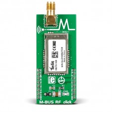
M-BUS RF click
The module has specified serial data rates of up to 115.2 Kbps and radio data rates of 2.4, 4.8 and 19.2 kbps. For security, the wireless signal has AES and NRZ encryption. Output power is from 125 mW to 631 mV (28dBm). According to the vendor’s data sheet, the module has wireless range of up to 20 km.
Short for Meter-Bus, this protocol was designed for the remote reading of gas or electricity meters, but it’s also suitable for alarm systems, illumination installations, heating control and more.
M-BUS RF click communicates with the target MCU through the mikroBUS™ UART interface, with additional functionality provided by RESET, RTS, and CTS pins. The board is designed to use a 3.3 power supply only.
Specification
| Type | RF Sub 1GHz |
| Applications | Wireless M-BUS was designed for gas and water meter applications |
| On-board modules | Telit ME70-169 RF |
| Key Features | Data rates: 115.2 Kbps serial; 2.4, 4.8 and 19.2 kbps radio |
| Key Benefits | Specified range of up to 20km, Wide area coverage |
| Interface | GPIO,UART |
| Input Voltage | 3.3V |
| Compatibility | mikroBUS |
| Click board size | L (57.15 x 25.4 mm) |
Features and usage notes
According to the vendor’s data sheet, the module has wireless range of up to 20 km (an external antenna is required).
Short for Meter-Bus, this protocol was designed for remote reading of gas or electricity meters in Europe, but it’s also suitable for alarm systems, illumination installations, heating control and more.
Devices that communicate with wireless M-Bus modules are classified as either meters or ‘other‘ devices. There is a total of six different M-Bus modes:
- Mode S ‘Stationary
- Mode T ‘frequent Transmit
- Mode R2 ‘frequent Receive
- Mode C ‘Compact
- Mode N ‘Narrowband VHF
- Mode F ‘Frequent receive and transmit
The working of all six modes is explained in detail in the learn.mikroe.com article on M-Bus.
Telit also provides a M-Bus guide which provides an Learn article explaining the MikroElektronika M-BUS library overview of the standard.
Programming
This example sets the M-Bus up for transmitting some data with a length field activated.
 1 #include <stdint.h>
 2 #include <stdbool.h>
 3 #include <stddef.h>
 4 #include "mbus_hw.h"
 5
 6 sbit MBUS_RST    at GPIOC_ODR.B2;
 7 sbit MBUS_RTS    at GPIOD_ODR.B13;
 8 sbit MBUS_CTS    at GPIOD_ODR.B10;
 9
10 bool my_receive_flag = false;     //Extern for knowing when packet is received from another M-Bus RF click
11
12 void system_setup( void );
13
14 void main()
15 {
16     //Local Declarations
17     transmit_frame_t *transmit_frame;
18
19     // Malloc space for the Transmit Frame
20     MM_Init();
21     transmit_frame = Malloc( sizeof( transmit_frame_t ) );
22     // Setup GPIOs, communication pins, interrupts, e.t.c.
23     system_setup();
24
25
26     //Initialize Conifguration Mode
27     UART1_Write_Text( "Entering Config Modern" );
28     mbus_at_init();
29
30     // Set MBUS Mode
31     UART1_Write_Text( "Setting MBUS Modern" );
32     check_status( mbus_set_mbus_mode( ROLE_N1_METER ) );
33
34     // Set RX / TX formats
35     check_status( mbus_set_serial_tx_format( LENGTH_TX ) );   // TX Format must have Length.. so that sending / receiving works properly
36
37     //Sending some data...
38     UART1_Write_Text( "rnrn Sending Frame Of Data...rnrn" );
39     // Set OP Mode
40     check_status( mbus_op_init() );
41     //Send Frame
42     sprintf( transmit_frame->data_field, "My Name is Engineer and I am %d Years Old.", 22 );
43     transmit_frame->length_field = strlen( transmit_frame->data_field );
44     mbus_send_frame( transmit_frame, 1 );              /**< Using length field for TX format, so not length needed */
45
46     while ( 1 );
47 }
48
49 void system_setup( void )
50 {
51     GPIO_Digital_Output( &GPIOC_BASE, _GPIO_PINMASK_2  );       /**< Reset pin Output */
52
53     UART1_Init_Advanced( 9600,  _UART_8_BIT_DATA,               /**< UART for Terminal */
54                          _UART_NOPARITY,
55                          _UART_ONE_STOPBIT,
56                          &_GPIO_MODULE_USART1_PA9_10 );
57     Delay_ms(300);
58
59     UART3_Init_Advanced( 19200, _UART_8_BIT_DATA,               /**< UART for MBus */
60                          _UART_NOPARITY,
61                          _UART_ONE_STOPBIT,
62                          &_GPIO_MODULE_USART3_PD89);
63     Delay_ms(300);
64
65     mbus_init();                                                /**< Initialize MBus HAL Layer */
66     Delay_ms(300);
67
68     RXNEIE_USART3_CR1_bit = 1;
69     NVIC_IntEnable( IVT_INT_USART3 );
70     EnableInterrupts();
71 }
72
73 void LO_RX_ISR() iv IVT_INT_USART3 ics ICS_AUTO
74 {
75     mbus_rx_isr( USART3_DR );
76 }
Code examples that demonstrate the usage of LED Ring click with MikroElektronika hardware, written for mikroC for ARM, PIC, and FT90x are available on Libstock.
Downloads
Enter the code in the box below:


