LSM6DSL click
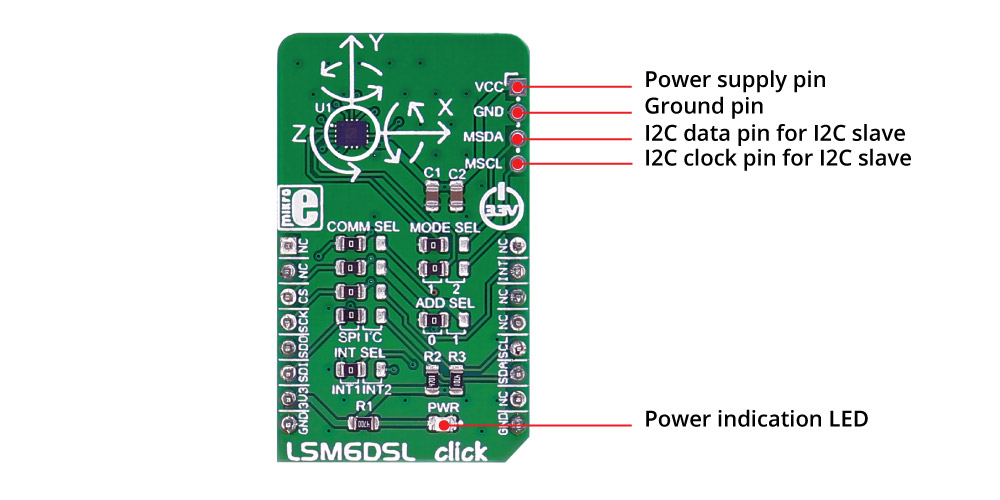
LSM6DSL click measures linear and angular velocity with six degrees of freedom. It carries the LSM6DSL high-performance 3-axis digital accelerometer and 3-axis digital gyroscope. The click is designed to run on a 3.3V power supply. LSM6DSL click communicates with the target microcontroller over SPI or I2C interface, with additional functionality provided by the INT pin on the mikroBUS™ line.

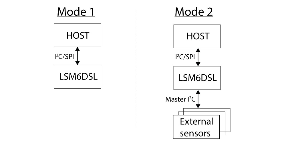
Mode 1: I2C slave interface or SPI serial interface is available.
Mode 2: I2C slave interface, or SPI serial interface and I2C interface master for external sensor connections, are available.

LSM6DSL inertial module features
The LSM6DSL is a system-in-package featuring a 3D digital accelerometer and a 3D digital gyroscope performing at 0.65 mA in high-performance mode and enabling always-on low-power features for an optimal motion experience.

The event-detection interrupts enable efficient and reliable motion tracking and contextual awareness, implementing hardware recognition of free-fall events, 6D orientation, click and double-click sensing, activity or inactivity, and wakeup events
The LSM6DSL has a full-scale acceleration range of ±2/±4/±8/±16 g and an angular rate range of ±125/±245/±500/±1000/±2000 dps (degrees per second).
Specifications
| Type | Motion |
| Applications | Motion tracking and gesture detection, indoor navigation, vibration monitoring and compensation, etc. |
| On-board modules | LSM6DSL |
| Key Features | Power consumption: 0.4 mA in combo normal and 0.65 mA in combo high-performance mode; hard, soft ironing for external magnetic sensor corrections |
| Interface | I2C,SPI |
| Input Voltage | 3.3V |
| Click board size | M (42.9 x 25.4 mm) |
Pinout diagram
This table shows how the pinout on LSM6DSL click corresponds to the pinout on the mikroBUS™ socket (the latter shown in the two middle columns).
Jumpers and settings
| Designator | Name | Default Position | Default Option | Description |
|---|---|---|---|---|
| JP1 | COMM SEL | Left | SPI | Communication Interface Selection SPI/I2C, left position SPI, right position I2C |
| JP2 | COMM SEL | Left | SPI | Communication Interface Selection SPI/I2C, left position SPI, right position I2C |
| JP3 | COMM SEL | Left | SPI | Communication Interface Selection SPI/I2C, left position SPI, right position I2C |
| JP4 | INT SEL | Left | INT1 | Interrupt selection INT1/INT2, left position INT1, right position INT2 |
| JP5 | COMM SEL | Left | SPI | Communication Interface Selection SPI/I2C, left position SPI, right position I2C |
| JP6 | MODE SEL | Left | 1 | Mode Selection 1/2, left position 1, right position 2 |
| JP7 | MODE SEL | Left | 1 | Mode Selection 1/2, left position 1, right position 2 |
| JP8 | ADD SEL | Left | 0 | I2C slave address selection 0/1, left position 0, right position 1 |
Programming
Code examples for LSM6DSL click, written for MikroElektronika hardware and compilers are available on Libstock.
Code snippet
The following code snippet initializes the module, the driver, and peripherals, and then outputs the measured data to UART every two seconds.
01 void main()
02 {
03     char txt [100];
04     float x,y,z;
05
06     systemInit();
07     LSM6DSL_initDriver(SPI3_Write, SPI3_Read);
08     UART1_Write_Text ("rnInitialized");
09
10     /*
11      * Starts measurements for acceleration and rotation at specified
12      * rate (104 HZ) and selected full-scale (+-2G, +-245DPS).
13      */
14     LSM6DSL_configureRead (CONFIG_ACCELERATION, ODR_104_HZ | FULLSCALE_A_2);
15     LSM6DSL_configureRead (CONFIG_ROTATION, ODR_104_HZ | FULLSCALE_R_245);
16     while( 1 )
17     {
18          UART1_Write_Text ("rnrnAcceleration values in mili-Gs:");
19          LSM6DSL_readAccelerationXYZ (&x, &y, &z, FULLSCALE_A_2);
20          sprintf (txt, "rnX: %.2f, t Y:%.2f, t Z: %.2f", x,y,z);
21          Uart1_Write_Text (txt);
22
23          UART1_Write_Text ("rnRotation values in degrees per second:");
24          LSM6DSL_readRotationXYZ (&x, &y, &z, FULLSCALE_R_245);
25          //Values are read in mili-degrees per second, so they need to be divided by 1000
26          sprintf (txt,
27           "rnPitch: %.2f, t Roll:%.2f, t Yaw: %.2f", x/1000,y/1000,z/1000);
28          Uart1_Write_Text (txt);
29
30          delay_ms (2000);
31     }
32 }
Downloads
mikroBUS™ Standard specificationLSM6DSL click schematic
LSM6DSL datasheet
Enter the code in the box below:


