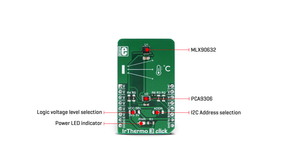
IrThermo 3 Click
Featuring high measurement resolution, reasonably accurate IR sensor, good precision within the specified temperature range, optical filtering of the visible light spectrum, EEPROM with factory calibration parameters, a simple interface that makes it really easy to integrate (only I2C related and power supply pins), and some other useful features, this device is an ideal solution for developing contactless temperature measurement applications. It can be used for industrial temperature control of moving parts which are hard to reach, general purpose industrial applications, air conditioning devices, and similar applications that require accurate temperature measurement in hard to reach or hazardous places.
How does it work?
IRThermo 3 click uses the MLX90632 FIR sensor from Melexis as the contactless temperature sensor. This sensor is a thermopile IR sensor. A thermopile sensor is actually a serially connected thermocouple array, with hot junctions located on the heat absorbing membrane. The cold junctions are located on a cold base, providing the reference point for generating the voltage. Due to the low-temperature capacity of the membrane, it will react to the heat radiation, generating voltage via the thermoelectric effect. The ASSP circuitry of the MLX90632 sensor filters and amplifies the sensor signal, preventing interferences from external sources, such as localized thermal variations (air turbulence, or thermal differences across the sensor itself) to affect the measurement, yielding the highest accuracy of up to ±1℃. However, excessive disturbances and variations will affect the accuracy. The device is driven by a state machine, which controls the operation of several internal sections: thermal sensors, programmable gain amplifier, ADC converter, digital filtering, memory, and communication sections.

The MLX90632 FIR sensor is factory calibrated in wide temperature range: -20°C to 80°C for ambient (sensor) temperature and --20°C to 200°C for the object temperature. An integrated thermal sensor allows ambient temperature measurement independently of the thermopile itself, allowing accurate calibration calculations to be performed.
EEPROM area with 256 locations of 16-bit words contains the calibration constants and trimming values. Along with the measurement from the integrated ambient temperature sensor (which measures the temperature of the sensor itself), the EEPROM information is used in the calculations. Formulas for the calculations can be found in the MLX90632 datasheet, and the host MCU should contain a firmware which processes the raw data from the sensor, by applying the calculations. The measurement data is stored in RAM locations, which is 96 16-bit words long. The rest of the RAM can be used for storing temporary results or some other auxiliary data.
The STATUS register offers information about the status: the device is busy, EEPROM busy, data is ready and so on. The CONTROL register sets operating modes and initiates measurement while in a SLEEP mode. The last register controls the I2C slave address LSB and these three registers are located in the REGISTERS memory area. The entire memory map with the detailed information about all the EEPROM and register locations is provided in the MLX90632 datasheet.
There are three modes of operation and depending on the working conditions, the appropriate mode can be selected in the CONTROL register:
SLEEP mode - or SLEEPING STEP mode uses the least power of all modes. The device turns off unneeded sections until a command is received via the CONTROL register (SOC bit). Upon receiving the command, device powers on, performs a measurement and reverts back to the SLEEP mode.
STEP mode uses more power as the device remains powered. The actual measurement is paused until a command is received (SOC bit of the CONTROL register). Upon receiving the command, the device performs a measurement and waits for the next command.
CONTINUOUS mode performs measurements continuously. This mode consumes the most power, but the new data is constantly gathered, providing most accurate measurement with no lag. The device can be configured to have high refresh rates (down to 16ms). The default refresh rate is 0.5s.
There are two SMD jumpers on this Click board™. One jumper is used to set the LSB of the I2C address of the device and it is labeled as the ADDR. The other SMD jumper is labeled as the VCC SEL and it is used to provide reference voltage for the PCA9306, a bi-directional I2C level shifter so that the Click board™ can be interfaced with both 3.3V and 5V MCUs.
Specifications
| Type | Temperature |
| Applications | It can be used for an accurate contactless thermal measurement, temperature control of moving and hard to reach parts, general purpose industry applications, air conditioning devices, and similar applications |
| On-board modules | MLX90632, an FIR sensor, from Melexis; PCA9306, a bi-directional I2C bus level translator from Texas Instruments |
| Key Features | High measurement resolution, reasonably sensitive IR sensor, good precision within the specified temperature range, optical filtering of the visible light spectrum, simple 5-pin interface, EEPROM with factory calibration parameters, and more |
| Interface | I2C |
| Input Voltage | 3.3V,5V |
| Click board size | M (42.9 x 25.4 mm) |
Pinout diagram
This table shows how the pinout on IrThermo 3 click corresponds to the pinout on the mikroBUS™ socket (the latter shown in the two middle columns).
Onboard settings and indicators
| Label | Name | Default | Description |
|---|---|---|---|
| PWR | PWR | - | Power LED indicator |
| VCC SEL | VCC SEL | Left | Power supply voltage selection: left position 3.3V, right position 5V |
Software support
We provide a library for the IrThermo3 Click on our LibStock page, as well as a demo application (example), developed using MikroElektronika compilers. The demo can run on all the main MikroElektronika development boards.
Library Description
The library performs IR and temperature measurement. The sensor measures the temperature of the detected object (body) and measures the ambient temperature. For more details, see the documentation.
Key functions :
void irthermo3_init()- Function for initialization chipfloat irthermo3_getAmbientTemperature()- Function for reading the ambient temperaturefloat irthermo3_getObjectTemperature()- Function for reading Object temperature
Example description
The application is composed of three sections :
- System Initialization - Initializes I2C module
- Application Initialization - Driver init and chip initialization
- Application Task - Reads the ambient temperature and temperature of the object every 400ms.
void applicationTask()
{
 ambientTemp = irthermo3_getAmbientTemperature();
 mikrobus_logWrite(" Ambient temperature : ",_LOG_TEXT);
 FloatToStr(ambientTemp, demoText);
 mikrobus_logWrite(demoText,_LOG_LINE);

 objectTemp = irthermo3_getObjectTemperature();
 mikrobus_logWrite(" Object temperature :",_LOG_TEXT);
 FloatToStr(objectTemp, demoText);
 mikrobus_logWrite(demoText, _LOG_LINE);

 mikrobus_logWrite(" ",_LOG_LINE);
 Delay_ms(1000);
}
The full application code, and ready to use projects can be found on our
LibStock page.
Other mikroE Libraries used in the example:
- I2C
- Conversions
Additional notes and information
Depending on the development board you are using, you may need USB UART click, USB UART 2 click or RS232 click to connect to your PC, for development systems with no UART to USB interface available on the board. The terminal available in all MikroElektronika compilers, or any other terminal application of your choice, can be used to read the message.
mikroSDK
This click board is supported with mikroSDK - MikroElektronika Software Development Kit. To ensure proper operation of mikroSDK compliant click board demo applications, mikroSDK should be downloaded from the LibStock and installed for the compiler you are using.
For more information about mikroSDK, visit the official page.
Downloads
mikroBUS™ Standard specificationIrThermo 3 click: 2D and 3D files
Enter the code in the box below:


