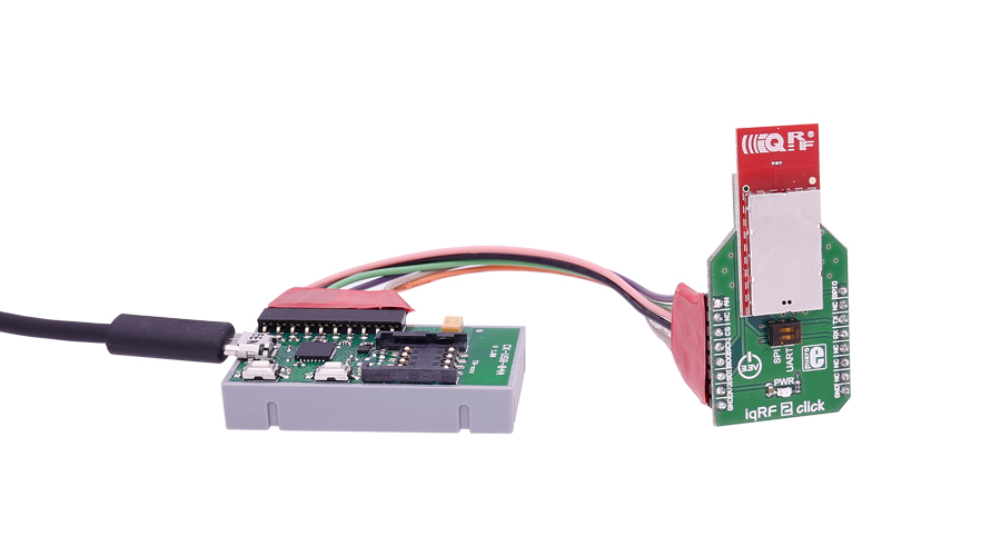
IQRF 2 click
IQRF 2 click carries the DCTR-72DAT RF transceiver, operating in the 868/916 MHz frequency. The click is designed to run on a 3.3V power supply. It communicates with the target microcontroller over SPI or UART interface, with additional functionality provided by the following pins on the mikroBUS™ line: AN, PWM.
Module features
DCTR-72DAT is an RF transceiver operating in the 868/916 MHz license-free ISM (Industry, Scientific, and Medical) frequency band. Its highly integrated ready-to-use design containing MCU, RF circuitry, serial EEPROM and optional onboard antenna requires no external components.
How the click works
The DCTR-72DAT module's highly integrated ready-to-use design containing MCU, RF circuitry, integrated LDO regulator, serial EEPROM, optional temperature sensor and optional onboard antenna requires no external components.
It has extended RF power results in higher RF range. The ultra-low power consumption fits for battery powered applications.
The module with a built-in operating system significantly reduces application development time. Optional DPA framework supports applications even without programming.

To upload application codes in DCTRs and configure DCTR parameters, CK-USB-04A kit is intended. When the application is uploaded to the IQRF it can be put in microBUS™ socket and communicate with it with MCU.
To upload the firmware put the jumpers in the SPI position.
To use our LibStock library examples the jumpers need to be in UART position.
Specifications
| Type | RF Sub 1GHz |
| Applications | Point-to-point or network wireless connectivity, Telemetry, AMR (automatic meter reading), WSN (wireless sensor network), Building automation, Street lighting control, etc. |
| On-board modules | DCTR-72DAT RF transceiver |
| Key Features | Selectable RF band 868 / 916 MHz, multiple channels |
| Interface | UART,Analog,GPIO,SPI |
| Input Voltage | 3.3V |
| Compatibility | mikroBUS |
| Click board size | M (42.9 x 25.4 mm) |
Pinout diagram
This table shows how the pinout on IQRF 2 click corresponds to the pinout on the mikroBUS™ socket (the latter shown in the two middle columns).
Programming
Code examples for iqRF click, written for MikroElektronika hardware and compilers are available on Libstock.
Code snippet
This code snippet contains receiver and transmitter code for IQRF 2 click board working with Thermo K click. When in transmit mode, MCU reads temperature from Thermo K and if certain threshold has been reached, byte data is sent to IQRF board via UART communication. Then, iqRF is broadcasting that byte to every other iqRF within range. Every Other IQRF click board is receiving that byte via RF communication and sending data to his local MCU via UART. Every event is displayed on easyTFT.
01 while(1)
02   {
03     #ifdef __TX__
04     ////////////////////////////////////////
05     status = &Read_MCP9600_Status;
06     Temp_Data_Ready = (status & 0x40);
07
08     temp =  Read_Temperature();
09
10     if (Temp_Data_Ready)
11     {                                        // Check is Temperature Data ready
12       sprintf(txt, "%2.1f  C", temp);        // Format Temperature Data and store it to txt
13       res = strcmp(txt,old_txt);             // Compare old_txt and txt
14
15       if(res != 0)                           // If old_txt and txt are not equal
16       {
17         updateLabel(txt, 135, 90, lab1);     // Write temperature value on display
18         strcpy(old_txt,txt);                 // Copy txt to old_txt string array
19       }
20     }
21
22     if (temp <= LOW_TEMP_POINT)              // If low temperature point has been reached
23     {
24      if (!low_point_reached)
25      {
26       UART3_Write_Text("L");                 // Send byte via UART
27      }
28      low_point_reached = true;
29
30     }
31     else if (temp >= HIGH_TEMP_POINT)        // If high temperature point has been reached
32     {
33      if(!high_point_reached)
34      {
35       UART3_Write_Text("H");                 // Send byte via UART
36      }
37      high_point_reached = true;
38
39     }
40     else
41     {
42      low_point_reached = false;
43      high_point_reached = false;
44     }
45     Delay_ms(500);
46   #endif
47   ////////////////////////////////////////
48   #ifdef __RX__
49
50     TFT_Set_Font(&HandelGothic_BT21x22_Regular, CL_BLACK, FO_HORIZONTAL);
51
52     // Writing warnings on display
53     if(high_point_reached)
54     {
55      TFT_Set_Font(&HandelGothic_BT21x22_Regular, CL_RED, FO_HORIZONTAL);
56      high_point_reached = false;
57      TFT_Write_Text("HIGH ", 130, 100);
58      Delay_ms(2000);
59      TFT_Set_Font(&HandelGothic_BT21x22_Regular, CL_WHITE, FO_HORIZONTAL);
60      TFT_Write_Text("HIGH ", 130, 100);
61     }
62     if(low_point_reached)
63     {
64      TFT_Set_Font(&HandelGothic_BT21x22_Regular, CL_BLUE, FO_HORIZONTAL);
65      low_point_reached = false;
66      TFT_Write_Text("LOW", 130, 100);
67      Delay_ms(2000);
68      TFT_Set_Font(&HandelGothic_BT21x22_Regular, CL_WHITE, FO_HORIZONTAL);
69      TFT_Write_Text("LOW ", 130, 100);
70     }
71   #endif
72   }
73
74 }
Downloads
mikroBUS™ Standard specificationEnter the code in the box below:


