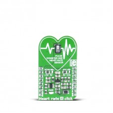
Heart rate 4 click
Heart rate 4 click carries the MAX30101 high-sensitivity pulse oximeter and heart-rate sensor from Maxim Integrated. The click is designed to run on either 3.3V or 5V power supply. It communicates with the target MCU over I2C interface, with additional functionality provided by INT pin on the mikroBUS™ line.
MAX30101 sensor features
The MAX30101 is an integrated pulse oximetry and heart-rate monitor module. It includes internal LEDs, photodetectors, optical elements, and low-noise electronics with ambient light rejection.
The MAX30101 integrates red, green, and IR (infrared) LED drivers to modulate LED pulses for SpO2 and HR measurements. The LED current can be programmed from 0 to 50mA with proper supply voltage.
The device includes a proximity function to save power and reduce visible light emission when the user’s finger is not on the sensor.
The MAX30101 has an on-chip temperature sensor for calibrating the temperature dependence of the SpO2 subsystem. The temperature sensor has an inherent resolution 0.0625°C.
Pulse oximetry or SpO2
Oxygen-saturated blood absorbs light differently than unsaturated blood. Pulse oximeters measure the oxygen saturation in one’s blood. Or to put it more precisely the percentage of hemoglobin molecules in blood that is saturated with oxygen.
In a healthy adult, this readings go from 94% to 100%.
How the sensor works
Since oxygen-saturated blood absorbs more infrared light than red light, and unsaturated blood absorbs more red light than infrared light, the SpO2 readings are calculated by the comparison of the amount of these two types of light.
It is best to use your finger for measurement.
The same sensor as Hexiwear
Did you know that this click carries the same sensor as Hexiwear?
When you place your wrist or fingertip over the slit on Hexiwear, the MAX30101 sensor measures the light absorbance of pulsing blood through a photodetector and derives heart-rate info. Current firmware version is able to show rough estimates.
MikroPlot
You can use the MikroPlot visualization tool (Windows) to generate a graph from the data sent from the MCU.
A UART-USB connection is required.
Specifications
| Type | Biomedical |
| Applications | wearable devices, fitness assistant devices, biomedical devices, etc. |
| MCU | MAX30101 heart-rate sensor |
| Key Features | Pulse oximetry or SpO2, low power consumption, programmable sample rate |
| Interface | I2C,GPIO |
| Input Voltage | 3.3V or 5V |
| Compatibility | mikroBUS |
| Click board size | M (42.9 x 25.4 mm) |
Pinout diagram
This table shows how the pinout on Heart rate 4 click corresponds to the pinout on the mikroBUS™ socket (the latter shown in the two middle columns).
Jumpers and settings
| Designator | Name | Default Position | Default Option | Description |
|---|---|---|---|---|
| J2A | VLED | LEFT | 5V | With this jumper we determine the LED diodes supplied with 3.3V or 5V. |
Programming
Code examples for Heart rate 4 click, written for MikroElektronika hardware and compilers are available on Libstock.
Code snippet
This code snippet initializes the system and display, initializes the board and sets I2C registers. New data from the sensor is collected in a endless loop, via polling and sent via UART to MikroPlot when we are in active heart rate mode.
01  void main( void )
02   {
03     system_init();
04     display_init();
05     hr4_init();
06     hr4_set_registers();
07
08     TFT_Set_Font( &HandelGothic_BT21x22_Regular, CL_RED, FO_HORIZONTAL );
09     TFT_Write_Text( "Use MikroPlot Graph Generator", 10, 100 );
10     TFT_Set_Font( &HandelGothic_BT21x22_Regular, CL_BLUE, FO_HORIZONTAL );
11     TFT_Write_Text( "Place Finger On Sensor", 19, 170 );
12
13     while ( true )
14     {
15       // Clearing the interrupt by reading the Interrupt Status 1
16       if ( hr4_is_new_fifo_data_ready() & 0x1 ) read_f = true;
17
18       if ( read_f )                          // If INT was emitted
19       {
20          read_f = 0;
21
22          if ( !start_f )                     // First start
23          {
24             start_f = true;
25             InitTimer1();                    // Initializing Timer 1
26             LOG("STARTrn");                // Sending START command to uPlot
27          }
28
29          red_sample = hr4_read_red();        // Read RED sensor data
30
31          LongToStr(miliseconds_counter , txt_milis);
32          LongToStr(red_sample , txt_val);
33          Ltrim(txt_val);
34          Ltrim(txt_milis);
35
36          // If sample pulse amplitude is under threshold value ( proximity mode )
37          if ( red_sample > 0 && red_sample < 32000 )
38          {
39            stop_f = true;
40            if ( !no_finger_f )
41            {
42              TFT_Rectangle( 19, 170, 310, 200 );
43              TFT_Write_Text( "Place Finger On Sensor", 19, 170 );
44            }
45
46            no_finger_f = true;
47          }
48
49          // If finger is detected ( we are in active heart rate mode )
50          else if( red_sample != 0)
51          {
52              stop_f = false;
53
54              if ( no_finger_f )
55              {
56               TFT_Rectangle( 19, 170, 310, 200 );
57               TFT_Write_Text( "Generating Graph...", 19, 170 );
58              }
59
60              no_finger_f = false;
61
62              // Sending data to MikroPlot in format:[pulse_value, milis] via UART
63              LOG(txt_val);
64              LOG(",");
65              LOG(txt_milis);
66              LOG("rn");
67          }
68       }
69     }
70   }
Downloads
mikroBUS™ Standard specificationHeart rate 3 click Learn Tutorial
MAX30101 datasheet
MikroPlot Data Visualization Tool
Heart rate 4 click schematic
Enter the code in the box below:


