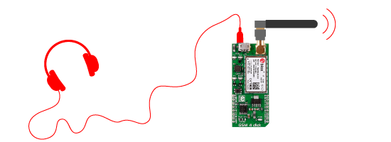
GSM 4 click
GSM 4 click is a mikroBUS™ add-on board that features the u-blox SARA-G3 series 2.5G GSM/GPRS cellular quad-band module. The SARA-G3 module has a miniature LGA (Land Grid Array) form factor as well as an RF transceiver and a power amplifier. With the click you can send and receives calls, SMS, and data. It can also be used as a standalone device tied to a PC through the onboard USB port - no development environment is needed.
GSM 4 click also has a 3.5mm jack for connecting headphones and a microphone. It runs on either 3.3V or 5V power supply, has an antenna connector and a SIM card socket. It communicates with the target MCU through UART.

Using GSM 4 click
In addition to the click you will need an SMA antenna, a SIM card, and a microphone or headset if you want to send and receive calls.
Free u-blox software
u-blox offers m-centre, a free evaluation software for all their cellular modules. It is an easy to use graphical interface where you can configure the module and save the changes on EPROM. You can also view and edit SIM phonebook entries, send text messages, and communicate with the wireless module using AT commands.
Global coverage
GSM 4 click has global quad-band coverage. The 900MHz and 1800MHz frequencies are used in most parts of the world (Europe, Africa, Middle East, Asia). The 850MHz and 1900MHz are used in North, South and Central America.
Power management
Two most power efficient modes on the module are idle mode and power off mode.
In idle mode the module typically uses 0.3mA, which is ideal for battery powered IoT devices and home automation systems. When the power saving mode is enabled, the module automatically enters the low power idle-mode to reduce current consumption. When in power off mode the module typically uses 36µA.
Additional information about the module
All SARA modules, including the one on this click, have a "nested design" — same form factor and footprint.
The module supports both IPv4 and IPv6 addresses.
Specifications
| Type | GSM |
| Applications | Remote monitoring automation, asset tracking, surveillance and security, home automation systems, point of sales terminals etc. |
| On-board modules | u-blox SARA-G3 series 2.5G GSM/GPRS cellular quad-band modul |
| Key Features | GSM Quad-band 850/1900, 900/1800 MHz, Maximum output power -8dBm, IPv4/IPv6 dual-stack |
| Key Benefits | Power consumption in idle-mode 0.3mA |
| Interface | GPIO,UART |
| Input Voltage | 3.3V or 5V |
| Compatibility | mikroBUS |
| Click board size | L (57.15 x 25.4 mm) |
Pinout diagram
This table shows how the pinout on GSM 4 click corresponds to the pinout on the mikroBUS™ socket.
Additional information about the click
The power button on the board is used to wake up the device if only the USB port is used.
The onboard zero ohm SMD jumper selects between 3.3V or 5V I/O voltage levels.
In order to avoid communication issues when using only USB, you should put the VCC jumper on 5V position. If you don't want to remove it from 3V3 just connect the 3V3 and 5V pin with a jumper wire.
Additional information about the module
All SARA modules, including the one on this click, have a "nested design" — same form factor and footprint.
SARA-G3 module provides a high-speed SIM/ME interface, including automatic detection and configuration of the voltage required by the connected (U)SIM card or chip. Both 1.8V and 3V SIM types are supported.
The module includes a High-Speed USB 2.0 compliant interface with maximum data rate of 480 Mb/s.
Specifications for GSM/GPRS Data
- GSM Quad-band 850/1900, 900/1800 MHz
- Maximum output power -8dBm
- IPv4/IPv6 dual-stack
- Embedded TCP/IP and UDP/IP stack
- Power consumption in idle-mode 0.5mA
- USB port for connecting to PC
- MikroBUS™ UART interface
- Runs on either 3.3V or 5V power supply
Programming
The demo uses generic AT parses also used with all previous GSM click boards. The example is a simple test procedure which rejects any incoming call.
- Maximum current detected : 220 mA – little lower than in case 3G Sara click
- Usable on : ARM, PIC, PIC32, AVR and FTDI compilers
Initialization routine for GSM4. Assignings gsm4_evn_default as default handler and gsm4_ev_ring function as handler for incoming calls. Routine also sends 3 AT commands.
 1 void gsm4_init( void )
 2 {
 3     engine_init( gsm4_evn_default );
 4
 5     at_cmd_save( "RING", 1000, NULL, NULL, NULL, gsm4_ev_ring );
 6
 7     at_cmd( "AT" );
 8     at_cmd( "AT+CSCS="GSM"" );
 9     at_cmd( "AT+CMGF=1" );
10 }
Downloads
mikroBUS™ Standard specificationEnter the code in the box below:


