DIGI POT 4 click
DIGI POT 4 click is a digitally controlled dual potentiometer, with the resistance of 10KΩ. It has a 10bit resolution which allows for a very smooth linear wiper positioning through 1024 steps. Digital wiper position can be controlled via SPI interface. DIGI POT 4 click also features a non-volatile durable EEPROM memory for storing the wiper position, which means that the device can restore its last position after the power on - just like its mechanical counterpart.
The main advantage of the digital potentiometers over the mechanical ones is that they can never wear out. The wiper position can be precisely programmed, and the wiper contact with the resistive coating can never be compromised by the influence of the dirt or moisture. Due to its low THD and good bandwidth, it can be used for digital volume control or a precise gain and offset adjustment. It can also be used as the LCD digital contrast control, and generally - whenever a precise dual digital voltage divider application is required.
How does the click work?
DIGI POT 4 click carries MAX5494, a 10bit dual, non-volatile, linear taper, digital potentiometer, from Maxim Integrated. This IC consists of the control logic and a resistors stream (i.e. 1024 equal resistors serially connected) through which the wiper is moving. The end-to-end resistance of the resistors on the used IC is 10KΩ. The wiper movement is done by writing 10bit data into the wiper registers, resulting in 1024 discrete positions the wiper can take. All three terminals of the digital pot are routed to the IC terminals and further to the onboard connectors, for easy and secure connecting to the rest of the circuit. The MAX5494 contains two such potentiometers, routed to the click board™ screw terminals. Depending on the output impedance to which the wiper is connected, it is possible that the voltage drop may occur while switching positions, therefore it is not recommended to use it as the variable resistor.
After the power on, the content of the EEPROM NV memory will be copied to the volatile RAM, used as the shift register for the wiper position. This volatile memory register directly controls the wiper position. The wiper can be positioned by writing data into this register. The EEPROM NV registers are only written if requested, by using the specific write command. This way, the EEPROM lifecycle is prolonged, although it can withstand up to 200000 read/write cycles.

All the communication with the control logic of the MAX5494 is done through the SPI, so all the SPI signals are routed to the appropriate mikroBUS™ pins. The CS pin is held high, preventing the SPI communication, so as always - to initialize the SPI communication, the CS pin needs to be pulled LOW by the MCU.
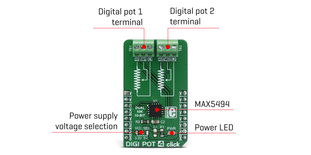
Besides two connectors used to connect the potentiometer terminals, the click board™ is equipped with the SMD jumper, used to choose between the 3.3V or 5V operating voltage.
Specifications
| Type | Digital potentiometer |
| Applications | It can be used for digital volume control or a precise gain and offset adjustment. It can also be used as the LCD digital contrast control, and generally - whenever a precise dual digital voltage divider application is required. |
| On-board modules | MAX5494, a 10bit dual, non-volatile, linear taper, digital potentiometer, from Maxim Integrated |
| Key Features | Accurate positioning of the wiper, via the 1024 different steps, non-volatile EEPROM memory used for recalling the wiper positions after the power on, very good bandwidth and low THD on input signals |
| Interface | SPI |
| Input Voltage | 3.3V or 5V |
| Click board size | M (42.9 x 25.4 mm) |
Pinout diagram
This table shows how the pinout on DIGI POT 4 click corresponds to the pinout on the mikroBUS™ socket (the latter shown in the two middle columns).
Onboard settings and indicators
| Label | Name | Default | Description |
|---|---|---|---|
| LD1 | PWR | - | Power LED indicator |
| J1 | VCC SEL | Left | Power supply voltage selection: left position 3V3, right position 5V |
| CN1 | TB1 | - | Digital potentiometer 1 terminal (H1,W1,L1) connection |
| CN2 | TB2 | - | Digital potentiometer 2 terminal (H2,W2,L2) connection |
Software support
We provide a library for DIGI POT 4 click on our LibStock page, as well as a demo application (example), developed using MikroElektronika compilers and mikroSDK. The provided click library is mikroSDK standard compliant. The demo application can run on all the main MikroElektronika development boards.
Library description
The library carries two functions which are sufficient to have complete control over DIGI POT 4 click.
Key functions:
void digipot4_writeReg(uint8_t Reg, uint16_t value);- Write data to wiper register
void digipot4_copyReg(uint8_t Reg);- Copy data to NV memory
Example description
The application is composed of three sections :- System Initialization - Initializes SPI module and sets CS pin as OUTPUT
- Application Initialization - DIGI POT 4 Driver initialization
- Application Task - (code snippet) - Sequentially sets the wiper position every second.
void applicationTask()
{
    digipot4_writeReg(_DIGIPOT4_WIPER_REG_1, 0);
    digipot4_writeReg(_DIGIPOT4_WIPER_REG_2, 0);
    Delay_1sec();
    digipot4_writeReg(_DIGIPOT4_WIPER_REG_1, 512);
    digipot4_writeReg(_DIGIPOT4_WIPER_REG_2, 512);
    Delay_1sec();
    digipot4_writeReg(_DIGIPOT4_WIPER_REG_1, 1023);
    digipot4_writeReg(_DIGIPOT4_WIPER_REG_2, 1023);
    Delay_1sec();
}
The full application code, and ready to use projects can be found on our LibStock page.
Additional notes and information
Depending on the development board you are using, you may need USB UART click, USB UART 2 clickor RS232 click to connect to your PC, for development systems with no UART to USB interface available on the board. The terminal available in all MikroElektronika compilers, or any other terminal application of your choice, can be used to read the message.
mikroSDK
This click board is supported with mikroSDK - MikroElektronika Software Development Kit. To ensure proper operation of mikroSDK compliant click board demo applications, mikroSDK should be downloaded from the LibStock and installed for the compiler you are using.
For more information about mikroSDK, visit the official page.
Downloads
mikroBUS™ standard specificationsEnter the code in the box below:


