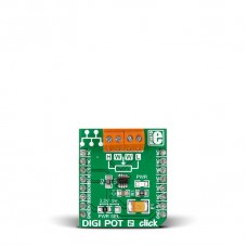
DIGI POT 2 click
Description
DIGI POT 2 click is a mikroBUS™ add-on board with a single channel digital potentiometer TPL0501 with 256 wiper positions. The IC has 100 kilo Ohms end-to-end resistance, with ±20% tolerance. The board features two pairs of screw terminals for interfacing with the IC DIGI POT 2 click communicates with the target MCU through the mikroBUS™ SPI pins (MISO, MOSI, SCK, CS). The board is designed to use either a 3.3 or a 5V power supply.
Specification
| Type | Digital potentiometer |
| Applications | Mechanical potentiometer replacement, sensor trimming and calibration and more |
| On-board modules | Digital potentiometer TPL0501 |
| Key Features | TPL0501 digital potentiometer, 256 wiper positions, 100 kilo Ohms end-to-end resistance |
| Key Benefits | Screw terminals simplify external connectivity, Small dimensions, easy to integrate in prototypes |
| Interface | SPI |
| Input Voltage | 3.3V or 5V |
| Compatibility | mikroBUS |
| Click board size | S (28.6 x 25.4 mm) |
Features and usage notes
Digital potentiometers are mixed signal devices intended as replacements for mechanical potentiometers. They can be used for consumer electronics, adjustable power supplies, precision calibration and sensor trimming.
The device has three terminals: High termianl, low terminal and a wiper terminal which is in-between. The wiper terminal is adjusted through SPI, moving through the specified 256 steps.
DIGI POT click can operate in several configurations:
- Voltage Divider mode
- Rheostat mode A
- Rheostat mode B
More details on each one can be found in the TPL0501 data sheet.
Digital potentiomenters can have any kind of interface. Not just knobs like mechanical potentiometers, but also buttons, capacitive inputs etc).
Another advantage of digital potentiometers is that you can create any desirable sweep profile (linear, digital or any other function).
The operating temperature of TPL0501 is between -40ºC to 125ºC. ESD performance is tested per JESD 22 requirements (human body model).
DIGI POT 2 click can be used both with a 3.3V or a 5V power supply, as determined by the position of the onboard jumper (soldered to 3.3V position by default).
Programming
The following code snippet shows a larger part of the DIGI POT 2 click example we supply:
 1 void main() {
 2
 3   Delay_ms(100);
 4
 5   while (1) {                            // Endless loop
 6
 7     DigPot_CS = 0;                       // Select PotentioMeter chip
 8     SPI1_Write(0);
 9     SPI1_Write(counter);
10
11     SPI1_Write(0x20);
12     SPI1_Write(counter);
13     DigPot_CS = 1;                       // Deselect PotentioMeter chip
14
15     adc_value = ADC_Read(1);             // Get 10-bit results of AD conversion
16     PORTD = (unsigned char)(adc_value >> 2);
17
18     if (PINB2_bit)                       // Press PB2 to decrease resistance between W and L
19       counter ++;
20     if (PINB3_bit)                       // Press PB3 to increase resistance between W and L
21       counter --;
22
23     Delay_ms(50);                        // Delay for debouncing
24
25   }
26 }
Code examples that demonstrate the usage of DIGI POT 2 click with MikroElektronika hardware, written for mikroC for are available on Libstock
Downloads
Enter the code in the box below:


