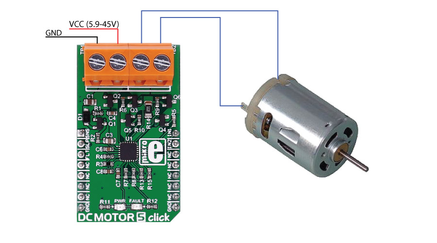
DC MOTOR 5 click
DRV8701 driver features
The DRV8701 is an H-bridge gate driver (also called a pre-driver or controller). The device integrates FET gate drivers in order to control four external NMOS FETs. The device can be powered with a supply voltage between 5.9V and 45V.
Internal protection functions are provided: under-voltage lockout, charge pump faults, overcurrent shutdown, short-circuit protection, pre-driver faults, and overtemperature.
How the click works
The motor's velocity and direction can be adjusted with two PWM input signal's.

Specifications
| Type | DC |
| Applications | Industrial brushed-DC motors, robotics, home automation, etc. |
| On-board modules | DRV8701 Brushed DC Motor Full-Bridge Gate Driver |
| Key Features | supply voltage between 5.9V and 45V |
| Interface | GPIO |
| Click board size | M (42.9 x 25.4 mm) |
Pinout diagram
This table shows how the pinout on DC MOTOR 5 click corresponds to the pinout on the mikroBUS™ socket (the latter shown in the two middle columns).
Buttons and LEDs
| Designator | Name | Type | Description |
|---|---|---|---|
| LD1 | PWR | LED | Power Indication LED |
| TB1 | VM | CD | Voltage input connector |
| TB2 | Out_M | CD | Motor connector |
Maximum ratings
| Description | Min | Typ | Max | Unit |
|---|---|---|---|---|
| Supply VOltage | 5.9 | 45 | V | |
| Source Current | 6 | 150 | mA | |
| Sink Current | 12.5 | 300 | mA | |
| Applied PWM signal | 100 | kHz | ||
| Operating ambient temperature | -40 | 125 | ℃ |
Programming
Code examples for DC MOTOR 5 click, written for MikroElektronika hardware and compilers are available on Libstock.
Code snippet
The following code snippet shows an example of DC motor 5 click usage. It will detect button press, and change the state of the control pins, putting the motor into one of the 4 possible states.
01 void main()
02 {
03     systemInit();
04
05    while (1)
06     {
07         // Coast
08         if (Button(&GPIOD_IDR, 1, 1, 1))
09         {
10             IN1_PIN = 0;
11             IN2_PIN = 0;
12         }
13
14        // Reverse
15         if (Button(&GPIOD_IDR, 2, 1, 1))
16         {
17             IN1_PIN = 0;
18             IN2_PIN = 1;
19         }
20
21        // Brake
22         if (Button(&GPIOD_IDR, 3, 1, 1))
23         {
24             IN1_PIN = 1;
25             IN2_PIN = 1;
26         }
27
28        // Forward
29         if (Button(&GPIOD_IDR, 4, 1, 1))
30         {
31             IN1_PIN = 1;
32             IN2_PIN = 0;
33         }
34
35    }
36 }
Downloads
mikroBUS™ Standard specificationDRV8701 datasheet
DC MOTOR 5 click schematic
Enter the code in the box below:


