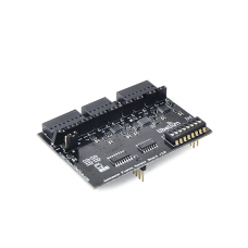
Waspmote Events Sensor Board
Product Code: CH-WEVENTS
The board allows simultaneous connection with up to 8 sensors whose outputs are compared with a threshold value and are combined in a OR logical gate which implements a change in the interruption bit which wakes the mote. The value of these thresholds is programmed by the microcontroller through the bus I2C as the system is controlled through digital potentiometers (digipots).The sensor that has interrupted the mote is identified in a shift register which can be read by Waspmote once it is in normal operation.
Documentation:
Waspmote Quick Tutorial
Waspmote Site
Waspmote Technical Guides
Sensor Boards Technical Guides
Networking Guides
Developers Forum
Videos
Articles
50 Applications with Waspmote
FAQ: Waspmote Vs. Arduino
Write a review
Your Name:
Your Review:
Note: HTML is not translated!
Rating:
Bad
Good
Enter the code in the box below:
© 2024, MG Automation Technologies. Powered by MG Super LABS.Find us on Google+
Designed with by Ish Gupta


