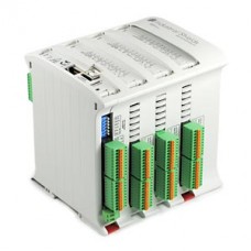
Configurable Arduino PLC for Industrial Uses
Modular PLC
This is the first equipment based on the Arduino technology fully designed for a professional use. This PLC is pre-configurable using a different number of inputs (from 6 to 36 inputs) and a different number of outputs (from 8 to 31 outputs). It also contains a lot of communication ports1 which provide more flexibility and control. The Configurable PLC allows you to expand up to 127 modules through I2C or RS485 or Ethernet (if choosed), which means that you can have until 7100 Inputs / Outputs in Master-Slave connections, additionally to sensors, etc…
Programming Software
This PLC can be programmed using the Arduino IDE platform. See the Documentation menu below to download the software for free.
Instantaneous connection and coding.
The Configurable PLC is programmed through the USB port. This PLC can also be programmed through Ethernet port remotely. This offers an immediate access to the program, maintain, and control. Also, you can continuously monitor the status of all the variables, inputs, outputs, etc. It is compatible with the Arbox and the Touchberry Pi with an instantaneous connection.
Arduino Board included
Inputs
– From 6 to 36 Outputs:
-
Analog (0-10Vdc, 10bit). Working also as Digital Inputs (5-24Vdc) configurables by software.
-
Digital Inputs (5-24Vdc).
-
Interrupt Inputs (5-24Vdc). “Can work like Digital Input (24Vdc)”
Outputs
– From 8 to 31 Outputs:
-
Analog (0-10Vdc, 8bit ). Working also as Digital Outputs (5-24Vdc) Configurable by Switch.
-
Digital Outputs (Optoisolated from 5 to 24Vdc).
-
Relay outputs (220Vac – 5A)
Communications
-
USB port (Working as serial communication). It is able also to program the PLC.
-
Ethernet port (Choose if you need to connect the PLC by Ethernet. You can also program the PLC* See how to do it on the blog).
-
I2C port. (Connectable with other Industrial Shields devices, sensors, I/Os modules, etc)
-
Serial TTL ports.
-
RS232 Port.
-
RS485 Port/ RS422 (RS485- Half/Full Duplex)
-
SPI external port (Using MOSI, MISO, SS pins from Arduino. (Available to work as digital Input/output at 5Vdc).
-
Standard COMMUNICATION protocols: TCP IP / MODBUS TCP / MODBUS RTU
-
WebServer capacity
Other technical specifications
RTC (Real Time Clock. NOTE: I2C port used. See pinout modification)
µSD Socket (using SPI port, chip select D53 pin. See pinout modification).
100x75x115mm
DIN Rail mounting.
Max consum.: 1.2A
Flash Memory: from 32 to 256kB (4-8kB for bootloader)
SRAM: from 2.5 to 8kB
EEPROM: from 1 to 4kB
Clock Speed: 16MHz
*See technical specification after choosing your PLC Configuration
|
Communication PORTS and main characteristics: |
Ethernet, RS485, RS232, Serial TTL, I2C, SPI, RTC(Real time Clock), µSD Socket, RS232, I2C, SPI (Can work as Serial TTL). |
|---|---|
|
Number of Inputs/Outputs on first modular board |
10 Inputs (10 Digital Inputs, 9 of which can work as Analog Input)/ 10 Outputs (10 Digital Outputs, 9 of which can work as Analog Output).*, 10 Inputs (10 Digital Inputs, 6 of which can work as Analog Input)/ 10 Outputs (8 Relay Outputs, 2 Analog Outputs).*, 13 Inputs (13 Digital Inputs, 6 of which can work as Analog Input)/ 8 Outputs (8 Digital Outputs, 3 of which can work as Analog Outputs).*, 6 Inputs (6 Digital Inputs, 4 of which can work as Analog Input)/ 11 Outputs (8 Relay Outputs,3 Digital Outputs, 2 of which can work as Analog Output).* |
|
Number of Inputs/Outputs on second modular board |
Not necessary, 13 Inputs (13 Digital Inputs, 6 of which can work as Analog Input)/ 8 Outputs (8 Digital Outputs, 3 of which can work as Analog Outputs).*, 6 Inputs (6 Digital Inputs, 4 of which can work as Analog Input)/ 11 Outputs (8 Relay Outputs,3 Digital Outputs, 2 of which can work as Analog Output).* |
|
Number of Inputs/Outputs on third modular board |
Not necessary, 13 Inputs (13 Digital Inputs, 6 of which can work as Analog Input)/ 8 Outputs (8 Digital Outputs, 3 of which can work as Analog Outputs).*, 6 Inputs (6 Digital Inputs, 4 of which can work as Analog Input)/ 11 Outputs (8 Relay Outputs,3 Digital Outputs, 2 of which can work as Analog Output).* |
Enter the code in the box below:


