Pololu Carrier for MQ Gas Sensors (Bare PCB Only)
Overview
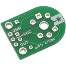
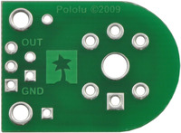
This breakout board is designed to work with any of the MQ-series gas sensors, simplifying the interface from 6 to 3 pins—ground, +5V VCC, and an analog voltage output—that are broken out with a 0.1" spacing, making the board compatible with 0.1" headers and standard breadboards and perfboards. This board has two mounting holes and provides convenient pads for mounting the gas sensor’s required sensitivity-setting resistor (referred to as RL in the sensor datasheet). All of the board’s traces are on the same side of the PCB, making it easy to see how the pads are connected.
The two mounting holes are intended to be used with #2 screws (not included).
Note that we also offer an alternate gas sensor breakout board that is more compact, with a diameter equal to that of the smaller gas sensor and the broken-out pins beneath the sensor.
|
|
Connections
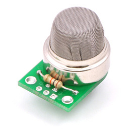
Connect VCC to 5 V, GND to ground, and OUT to an analog-to-digital converter (ADC). The board has two pairs of through-hole pins for the required (but not included) sensitivity-selecting resistor RL, providing two mounting options—horizontal or vertical—between GND and OUT as shown in the pictures below. The resistance of RL should be calculated using the datasheet for your particular gas sensor.
The MQ gas sensors have light to no polarity, so the gas sensor will work with the board all four ways it fits into the 6 pins (there are two possible orientations on each side of the board).
|
|
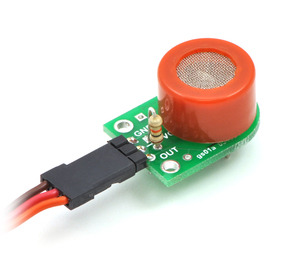
The picture to the right above shows a board with a 3×1 0.1" right-angle male header soldered to it, which allows a standard servo cableto be used to connect the board to your project.
Enter the code in the box below:


-80x80.jpg)
-80x80.jpg)


