Ultrasonic 2 Click
Featuring the advanced SoC which encompasses ultrasonic capsule drivers, very advanced DSP for signal processing, adjustable threshold settings, 128 bytes of RAM for storing echo recordings, easy to use UART interface with auto-baud rate detection, self-diagnostics, and more, Ultrasonic 2 click offers a complete solution perfectly suited for the rapid development of various applications that rely on an accurate and reliable range detection: park assist, collision detection, lane departure warning (LDW), and similar automotive-related applications, object distance and position sensing, presence and proximity detection, drone landing assist and obstacle detection applications, and all other applications that can benefit from a compact, reliable, and accurate range detection solution.
How does it work?
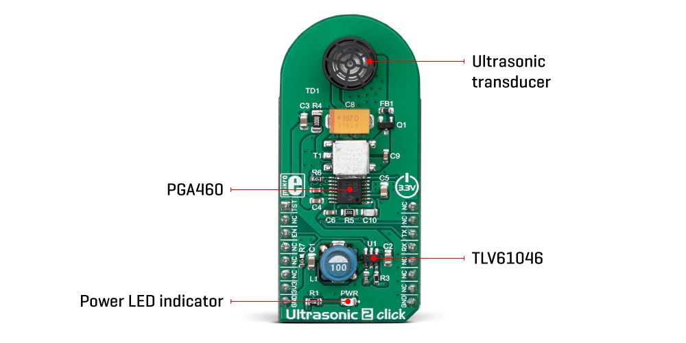
The main component of the Ultrasonic 2 click is the PGA460, an integrated ultrasonic signal processor and transducer driver, produced by Texas Instruments. This system-on-chip (SoC) device features a set of different devices, integrating them into a single IC: a low-noise analog front end (AFE) with a programmable time-varying gain stage, a digital signal processor (DSP), and an integrated transducer driver. An additional temperature sensor is also integrated into the SoC, which allows thermal compensation. The device uses the UART communication interface to exchange commands and data with the host microcontroller unit (MCU). More information on registers, data format through the UART, and more detailed explanation can be found in the PGA460 datasheet, in the download section below. However, Ultrasonic click is supported by the mikroSDK library which contains functions and initialization routines, which allow to directly obtain distance parameters of a detected object, greatly simplifying the design, and cutting time to market.

The PGA460 SoC is based on a SONAR principle: it produces an ultrasound pulse burst while recording the received echo response. The received echo signal is then processed and compared to a set of time-varying thresholds, stored in the non-volatile memory of the device. A time-variable gain stage allows the whole dynamic range of the A/D converter to be used, allowing accurate detection for both near-field and far-field objects: a higher gain is applied to echo responses coming from distant objects. Before the gain is applied, the echo response is processed by the second order bandpass IIR filter with selectable bandwidth, as well as the first order lowpass filter with selectable cutoff frequency, reducing any sounds and noises that might interfere with readings.
The PGA460 has the ability to produce an ultrasonic burst and record its echo response, which is similar to how SONAR operates. To allow ultrasonic pulses with high sound pressure level (SPL), Ultrasonic 2 click utilizes an output transformer, driven by the transducer driver section of the PGA460 SoC. The driver section is composed of a complementary driver pair, used to excite primary windings of the transformer. The secondary windings are directly connected to an ultrasonic transducer. The ultrasonic transducer can be both time-decoupled and temperature-decoupled, ensuring very reliable acquisition of the echo response.
Two sets of preset threshold and gain values are included in both cases when an ultrasonic burst is produced, and when the transducer is used only to record the response. In the second case, a separate ultrasonic burst source would still be required. The preset values are stored along with their time stamps, allowing them to be applied to specific time points of the echo recording. A linear interpolation is applied between consecutive points, allowing smooth transition over time. If the recorded echo response contains amplitude values that exceed the threshold value, a detection event will be recorded, along with the time code. After the burst-and-listen (or just listen) cycle is complete, the PGA460 device computes the distance, amplitude, and width of the echo, through the UART communication interface.
As mentioned before, threshold and gain preset values are stored in the non-volatile memory of the device, along with some other parameters (42 bytes of user EEPROM). This allows the configuration parameters to be preserved after the power cycle, allowing fast initialization. The user has the ability to adjust these values and fine-tunes the application responsiveness for the specific conditions in which it will be used.
Since the PGA460 SoC IC requires a slightly higher voltage level for its operation than it is available from the mikroBUS™ power rails, Ultrasonic 2 click is also equipped with the voltage boost IC. For this purpose, the TLV61046, a 28V output voltage boost converter from Texas Instruments. This voltage converter requires a minimum number of external components, which allows it to be implemented in a very small area of the PCB. This makes it a viable solution to be used alongside the PGA460 on the same Click board™. It is set to output approximately 7.5V on its output, an optimal voltage for operation of the PGA460. The transformer used to provide the necessary voltage for the ultrasonic transducer capsule is also included on the Click board™ along with the transducer capsule itself, making it ready to be used right out of the box.
Specifications
|
Type |
Various |
|
Applications |
It can be used for park assist, collision detection, lane departure warning (LDW), and similar automotive-related applications, object distance and position sensing, presence and proximity detection, drone landing assist and obstacle detection applications, etc. |
|
On-board modules |
PGA460, an integrated ultrasonic signal processor and transducer driver by Texas Instruments; TLV61046, a 28V output voltage boost converter by Texas Instruments |
|
Key Features |
A highly Integrated SoC with advanced DSP processing functions which allow very accurate and reliable object range detection, processed distance data available on the output, a complete ultrasonic range detection solution supported by software libraries for rapid development, non-volatile parameter storage for a fast initialization… |
|
Interface |
UART |
|
Input Voltage |
3.3V |
|
Click board size |
M (42.9 x 25.4 mm) |
Pinout diagram
This table shows how the pinout on the Ultrasonic 2 Click corresponds to the pinout on the mikroBUS™ socket (the latter shown in the two middle columns).
|
Notes |
Pin |
Pin |
Notes |
||||
|---|---|---|---|---|---|---|---|
|
Test |
TST |
1 |
AN |
PWM |
16 |
NC |
|
|
|
NC |
2 |
RST |
INT |
15 |
NC |
|
|
Power Enable |
EN |
3 |
CS |
RX |
14 |
TX |
UART Transmit |
|
|
NC |
4 |
SCK |
TX |
13 |
RX |
UART Receive |
|
|
NC |
5 |
MISO |
SCL |
12 |
NC |
|
|
|
NC |
6 |
MOSI |
SDA |
11 |
NC |
|
|
Power supply |
3V3 |
7 |
3.3V |
5V |
10 |
5V |
|
|
Ground |
GND |
8 |
GND |
GND |
9 |
GND |
Ground |
Onboard settings and indicators
|
Label |
Name |
Default |
Description |
|---|---|---|---|
|
LD1 |
PWR |
- |
Power LED indicator |
Software support
We provide a library for the Ultrasonic 2 click on our LibStock page, as well as a demo application (example), developed using MikroElektronika compilers. The demo can run on all the main MikroElektronika development boards.
Library Description
The library initializes and defines the UART bus driver and drivers that offer a choice for writing data on UART. The library includes the function for initialization device, TVG, communication, and Thresholds, configuration chip and enabling device. The user also has the function for set Ambient temperature which depends on the speed of sound, the function for reading ultrasonic measurement and device diagnostics.
Key functions:
-
void ultrasonic2_enable(uint8_t state)- Function for enable chip
-
void ultrasonic2_getUltrasonicMeasurement(uint8_t numObj, float *distOUT, uint16_t *widthOUT, uint8_t *ampOUT)- Function for getting ultrasonic measurement
-
void ultrasonic2_getDiagnostics(float *freqOUT, float *periodOUT, float *tempOUT, float *noiceOUT)- Function for reading diagnostics
Examples description
The application is composed of the three sections :
-
System Initialization - Initializes UART module and sets CS and AN pins as OUTPUT
-
Application Initialization - Driver initialization for powering the Click board, chip configuration and reading the sensor diagnosis.
-
Application Task - (code snippet) - Starts measuring and measures the distance of an object every 500 ms.
void applicationTask()
{
    ultrasonic2_startUltrasonicMeasurement(_ULTRASONIC2_DETECT_OBJECT_1);

    for (cnt = 0; cnt < _ULTRASONIC2_DETECT_OBJECT_1; cnt++)
    {
        ultrasonic2_getUltrasonicMeasurement(cnt, &distance, &width, &peak);
        Delay_ms(10);

        distance = distance * 100;
        if(distance < 300)
        {
            FloatToStr(distance, demoText);
            demoText[ 6 ] = 0;
            mikrobus_logWrite(" Distance (cm): ",_LOG_TEXT);
            mikrobus_logWrite(demoText,_LOG_LINE);
        }
    }
    Delay_ms( 500 );


}
-
An additional function is used to store responses.
void UART_RX_ISR()iv IVT_INT_USART3 ics ICS_AUTO
{
    if( RXNE_USART3_SR_bit )
    {
        char tmp = USART3_DR;
        ultrasonic2_getc(tmp);
    }
}
-
Notes: Bear in mind that any change in device initialization drastically changes the workload of the device and its measurement pattern. This library has been made according to Texas Instruments PGA460 chip library.
The full application code, and ready to use projects can be found on our LibStock page.
Other mikroE Libraries used in the example:
-
UART
Additional notes and information
Depending on the development board you are using, you may need USB UART click, USB UART 2 click or RS232 click to connect to your PC, for development systems with no UART to USB interface available on the board. The terminal available in all MikroElektronika compilers, or any other terminal application of your choice, can be used to read the message.
mikroSDK
This click board is supported with mikroSDK - MikroElektronika Software Development Kit. To ensure proper operation of mikroSDK compliant click board demo applications, mikroSDK should be downloaded from the LibStock and installed for the compiler you are using.
For more information about mikroSDK, visit the official page.
Downloads
mikroBUS™ Standard specification
Enter the code in the box below:


