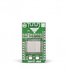
WiFi2 click
WiFi2 click features the HLK-M30 WiFi module with a built-in TCP/IP protocol stack. The click is designed to run on a 3.3V power supply; it communicates with the target MCU over an UART interface and the following mikroBUS™ pins: AN, RST.
TCP/IP client of server
WiFi2 click can be set up both as a TCP/IP client or server. You can configure it with either a static or dynamic IP address. Use the mikroBUS™ AN line (DEF on this click) to reset WiFi2 to default factory settings if needed.
Security and network protocols
WiFi2 click supports standard security authentication systems (WEP64/WEP128/ TKIP/ AES, WEP/WPA-PSK/WPA2-PSK); as well as multiple network protocols (TCP/UDP/ DHCP/DNS). All these features make WiFi2 click ideal for home automation applications, remote controls, telemetry etc.
PBC antenna
The click features a PCB trace antenna, designed for the 2400–2483.5 MHz frequency band.
Specification
| Type | Wi-Fi |
| Applications | WiFi2 click is simple to configure so is suitable for a wide range applications, including home automation, remote control and so on |
| On-board modules | HLK-M30 WiFi |
| Key Features | TCP/UDP/DHCP/DNS network protocols supported. Built-in EP64/WEP128/ TKIP/ AES, WEP/WPA-PSK/WPA2-PSK authentication |
| Key Benefits | Can be configured with a static IP address |
| Interface | GPIO,UART |
| Input Voltage | 3.3V |
| Compatibility | mikroBUS |
| Click board size | M (42.9 x 25.4 mm) |
Key features
- HLK-M30 module
- Supports 802.11b/g/n
- TCP/UDP/DHCP/DNS network protocols supported
- Built-in EP64/WEP128/ TKIP/ AES, WEP/WPA-PSK/WPA2-PSK authentication
- Interface: UART
- 3.3V power supply
Downloads
mikroBUS™ Standard specification
Pinout diagram
This table shows how the pinout on WiFi2 click corresponds to the pinout on the mikroBUS™ socket (the latter shown in the two middle columns).
Programming
This function powers on the WiFi2 click module and must be executed before any usage of the click board functionality.
01 void WiFi2_PowerON( void )
02 {
03     WiFi2_DEF  = 1;
04     WiFi2_RST  = 0;
05     WiFi2_TX   = 0;
06     WiFi2_RX   = 0;
07     delay_ms( 500 );
08     WiFi2_RST  = 1;
09     delay_ms( 100 );
10     WiFi2_TX   = 1;
11     delay_ms( 100 );
12 }
Enter the code in the box below:


