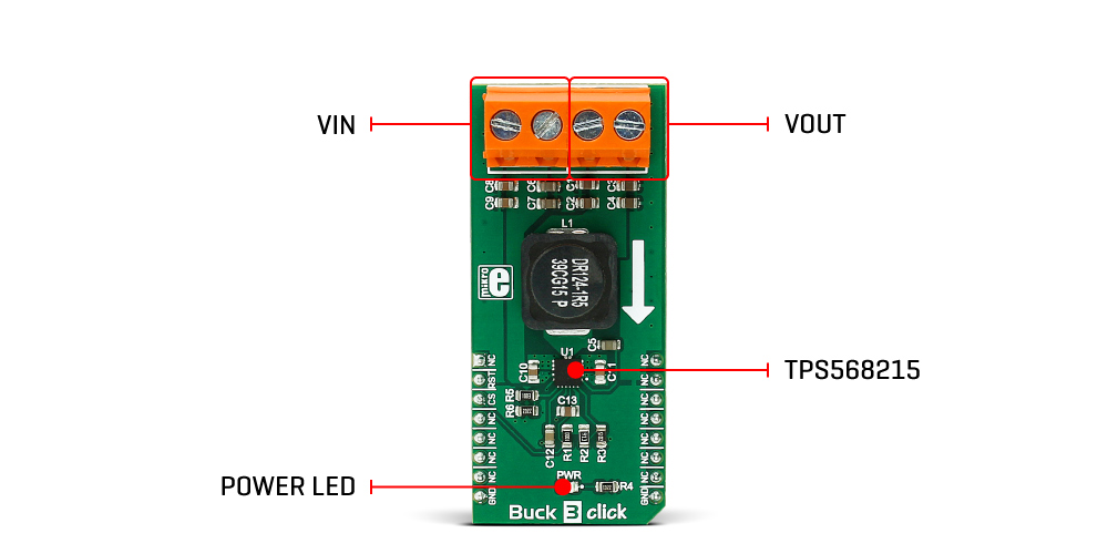
Buck 3 click
Buck 3 click is a very advanced synchronous step-down (buck) converter, which is designed to deliver noise and ripple-free voltage to highly sensitive applications, such as FPGA and high-performance DSP platforms. The onboard step-down converter IC integrates low RDSON MOSFETs, that allow high efficiency, and thus high current on the output - up to 8A. Buck 3 operates at 800kHz, allowing an optimal balance between the efficiency and the size of the used components. DCM mode ensures that the efficiency is maintained even while working with light loads.
Besides clean, noiseless and ripple-free 3.3V output provided by the proprietary D-CAP3™ PWM control mode for a fast transient response, this device also features overvoltage and undervoltage protection, thermal protection, current limiting, soft start function, and more. These features allow Buck 3 click to be used in a range of different applications, such as servers and storage devices, set-top boxes, telecom and networking, sensitive DSP and FPGA embedded applications, and similar applications that require a clean and regulated power supply.
How does it work?
Buck 3 click uses the TPS568215, a 4.5V to 17V Input, 8A synchronous step-down SWIFT™ converter from Texas Instruments. Its main features are the unparalleled ripple and noise-free operation, as well as the high efficiency throughout the whole load range, up to 8A. As such, it is suitable for powering up power demanding applications. Driven by the D-CAP3™ technology, the TPS568215 allows for a very low number of external components, maintaining an accurate voltage at the output. To further minimize the noise, the TPS568215 has separate grounds for the logic signal and the analog signal. The design of the Click board™ PCB ensures that the low noise operation is maintained within the specifications.

The onboard voltage divider connected to the MODE pin of the IC is used to set the device to work with the fixed PWM frequency of 800kHz, DCM/Eco-mode™ for light loads, and to set the limiting current to about 7A.
When the connected load is light enough, the ripple current valleys on the inductor coils will cross zero. Since the TPS568215 is set to operate in DCM/Eco-mode™, the device will start skipping PWM pulses, maintaining the efficiency that way. For regular loads, the device will be operated with the fixed frequency PWM signal, set by the MODE pin - 800kHz, providing low ripple and low noise output voltage.
The PGD (power good) pin is used to signalize the undervoltage or overvoltage status of the device. When the voltage on the feedback pin is between 97% and 107% of the nominal output voltage, this pin is de-asserted and pulled to a HIGH logic level by the onboard pull-up resistor. When a faulty condition occurs, this pin is driven to a LOW logic state. PGD pin is routed to the CS pin of the mikroBUS™
The EN pin is used to enable the device. Setting this pin to HIGH logic level (above 1.2V) will activate the internal switching circuitry. When the pin is set to a LOW logic level, the device is in STANDBY mode, and the power consumption is minimal. The EN pin is routed to thPinout diagrame mikroBUS™ AN pin.
This Click board™ is not powered up by the mikroBUS™ power rails. The power for the logic sections of the IC is supplied by the internal LDO output from the TPS568215 (VREG). This internal LDO is supplied by the input voltage, so the Buck 3 click will appear unpowered unless the external power supply is connected to the input terminal.
Buck 3 click has two 2-pole terminals, used to connect the external power supply and the load. These robust input and output screw terminals have cross-section dimensions which allow high currents to be connected, with no heating or damage.
Specifications
| Type | Buck |
| Applications | A perfect choice for step-down applications for embedded electronic devices, servers, routers, data storage devices, low power ICs, etc |
| On-board modules | TPS568215 4.5V to 17V input, 8A synchronous step-down SWIFT™ converter from Texas Instruments |
| Key Features | Eco-mode™ for the improved efficiency for light loads, D-CAP3™ technology for the low external components count, low noise and low output voltage ripple, very high efficiency allows current up to 8A |
| Interface | GPIO |
| Click board size | M (42.9 x 25.4 mm) |
Pinout diagram
This table shows how the pinout on Buck 3 click corresponds to the pinout on the mikroBUS™ socket (the latter shown in the two middle columns).
Buck 3 click electrical specifications
| Description | Min | Typ | Max | Unit |
|---|---|---|---|---|
| Input Voltage | -0.3 | - | 10 | V |
| Regulated output voltage | - | 3.3 | - | V |
| Current output | - | 8 | - | A |
Onboard settings and indicators
| Label | Name | Default | Description |
|---|---|---|---|
| LD1 | PWR | - | Power LED indicator |
Software support
We provide the library for Buck 3 click on our LibStock page, as well as the demo application (example), developed using MikroElektronika compilers and mikroSDK. The provided click library is mikroSDK standard compliant. The demo application can run on all the main MikroElektronika development boards.
Library Description
The library carries only two functions needed to control Buck 3 click.
Key functions:
uint8_t buck3_getState()- Checks the Power Good Indicator.void buck3_enable( uint8_t state )- Puts the device in working mode (enable).
Examples Description
The demo application is composed of three sections:
- System Initialization - Initializes the CS pin as INPUT and RST pin as OUTPUT.
- Application Initialization - Initializes the Driver init and puts the device in ACTIVE mode.
- Application Task - (code snippet) - Sequentially, each second, checks the status of the Buck 3 Click and if the overvoltage detected or device is under thermal shutdown
it logs a message on the USBUART.
Note: Open Drain Power Good Indicator, it is asserted low if the output voltage is out of PGOOD threshold, Overvoltage or if the device is under thermal shutdown, EN shutdown or during soft start. Once the FB pin voltage is between 93% and 107% of the internal reference voltage (VREF) the PGOOD is pulled high.
void applicationTask()
{
 statePG = buck3_getState();

 if (statePG == 0)
 {
 mikrobus_logWrite( "Overvoltage or thermal shutdown detected", _LOG_LINE );
 Delay_1sec();
 }
}
The full application code and ready-to-use projects can be found on our LibStock page.
Other MikroElektronika libraries used in the example:
- UART
Additional notes and information
Depending on the development board you are using, you may need USB UART click, USB UART 2 click or RS232 click to connect to your PC, for development systems with no UART to USB interface available on the board. The terminal available in all MikroElektronika compilers, or any other terminal application of your choice, can be used to read the message.
mikroSDK
This click board is supported by the mikroSDK - MikroElektronika Software Development Kit. To ensure proper operation of mikroSDK compliant click board demo applications, the mikroSDK should be downloaded from the LibStock and installed for the compiler you are using.
For more information about mikroSDK, visit the official page.
Downloads
Enter the code in the box below:


