3G-AA Click (United States)
Description
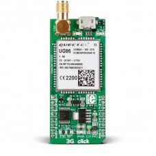
3G click (for USA) is a mikroBUS™ add-on board with Quectel’s UG95 3G UMTS/HSPA module. The board has a rich set of components to simplify development: an SMA connector, earphone/microphone jack, MicroUSB port, as well as a SIM card slot. The UG95 module specifies data rates of up to 7.2Mbps (HSPA), and 384Kbps (UMTS). The network protocol stack includes support for TCP, UDP, PPP, MMS, FTP, SMTP, SMTPS, HTTP, HTTPS, PING, and SSL. This version operates on American frequency bands (850/1900@UMTS). A Europe & Australia version of the same board is available separately. 3G click communicates with the target MCU through the mikroBUS™ UART interface (RX, TX), with additional functionality provided by STAT, PWRKEY, RTS, R1, and CTS pins. The board is designed to use 3.3V and 5V power supply. Note: Antenna sold separately.
Specification
| Type | GSM |
| Applications | Already in use for several years, 3G is set to surpass the GSM standard for wireless mobile communications |
| On-board modules | Quectel’s UG95 3G UMTS/HSPA module |
| Key Features | HSPA data rates: 7.2Mbps download, 5.76Mbps upload, Protocol stack: TCP/UDP/PPPI/MMS/FTP/SMTP/SMTPS/HTTP/HTTPS/PING/SSL |
| Key Benefits | On-board SMA connector, SIM card slot, Micro USB port, Eearphone/Mic jack, Backward compatible with GSM |
| Interface | GPIO,UART |
| Input Voltage | 3.3V or 5V |
| Compatibility | mikroBUS |
| Click board size | L (57.15 x 25.4 mm) |
Features and usage notes
Due to the nature of the protocol, 3G click comes in two different versions. The Europe and Australia version operates on the 900/2100@UMTS, 900/1800@GSM frequency band, while the USA version works on 850/1900@UMTS frequency band. The boards are otherwise identical. An onboard jumper allows you to choose the I/O voltage levels between 3.3V and 5V. Signal LEDs show the status of the data transmission. The following are data rates the UG95 module can achieve using various supported protocols: - HSPA: 7.2 Mbps (DL)/ 5.76 Mbps (UL) - UMTS: 384 Kbps (DL)/ 384 Kbps (UL) - GPRS: 85.6 Kbps (DL)/ 85.6 Kbps (UL) - EDGE: 236.8 Kbps (DL)
Programming
The demo initialises the TFT display and sets pins to operate in input direction. The main fucntion of the demo uses the polling method to check if inputs are on an active level. The TFT display shows the button state according to detect level.
This code snippet shows how easy it is to establish a connection with 3G click, and answer or hangup an incoming call.
  1 #include "3G_click_lib.h"
 2 #include "resources.h"
 3
 4 // TFT module connections
 5 unsigned int TFT_DataPort at GPIOE_ODR;
 6 sbit TFT_RST at GPIOE_ODR.B8;
 7 sbit TFT_RS at GPIOE_ODR.B12;
 8 sbit TFT_CS at GPIOE_ODR.B15;
 9 sbit TFT_RD at GPIOE_ODR.B10;
10 sbit TFT_WR at GPIOE_ODR.B11;
11 sbit TFT_BLED at GPIOE_ODR.B9;
12
13 sbit GSM_PWR at GPIOC_ODR.B2;
14 sbit GSM_CTS at GPIOD_ODR.B13;
15 sbit GSM_RTS at GPIOD_IDR.B10;
16
17 bool answer_call = false;
18 bool hangup_call = false;
19
20 void system_init( void );
21
22 void main()
23 {
24     system_init();
25     display_init();
26     click_3g_api_init();
27
28     while( 1 )
29     {
30         click_3g_process();
31
32         if( Button( &GPIOC_IDR, 9, 80, 1 ) )
33             answer_call = true;
34
35         if( Button( &GPIOC_IDR, 8, 80, 1 ) )
36             hangup_call = true;
37
38         if( answer_call )
39         {
40             click_3g_call_answer();
41             answer_call = false;
42         }
43
44         if( hangup_call )
45         {
46             click_3g_call_hangup();
47             hangup_call = false;
48         }
49     }
50 }
Downloads
Enter the code in the box below:


