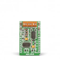
ADC click
Description
ADC click carries the MCP3204 12-bit Analog-to-Digital converter. The click is designed to run on 3.3V by default. Place PWR SEL SMD jumper to 5V position if used with 5V systems. It communicates with the target microcontroller over SPI interface.
MCP3204 features
MCP3204 Analog-to-Digital converter features 50k samples/second, 4 input channels and low power consumption (500nA typical standby, 2µA max).
Reading Analog inputs
There are four analog input screw terminals for each of the supported A/D channels. We added two more terminals for GND reference. Each analog input voltage is converted to an appropriate 12-bit digital value, which can be read using industry standard SPI communication interface.
Specifications
| Type | ADC |
| Applications | Board can be used in applications such as data acquisition, instrumentation, measurement, etc. |
| On-board modules | Analog-to-Digital Converter (ADC) MCP3204 |
| Key Features | 12-bit resolution of Analog-to-Digital conversion |
| Key Benefits | Low power consumption (500nA typical standby) |
| Interface | SPI |
| Input Voltage | 3.3V or 5V |
| Compatibility | mikroBUS |
| Click board size | M (42.9 x 25.4 mm) |
Pinout diagram
This table shows how the pinout on ADC click corresponds to the pinout on the mikroBUS™ socket (the latter shown in the two middle columns).
Jumpers and settings
| Designator | Name | Default Position | Default Option | Description |
|---|---|---|---|---|
| JP1 | PWR SEL | Left | 3V3 | Power Supply Voltage Selection 3V3/5V, left position 3V3, right position 5V |
| JP2 | Reference | VCC | 4.096V | Reference voltage selection |
There are two zero-ohm resistors (SMD jumpers): PWR SEL is used to determine whether 5V or 3.3V power supply is used, and REFERENCE to select either VCC or 4.096V as the voltage reference.
Downloads
LibStock: ADC click examplesEnter the code in the box below:


