ADC 18 CLICK
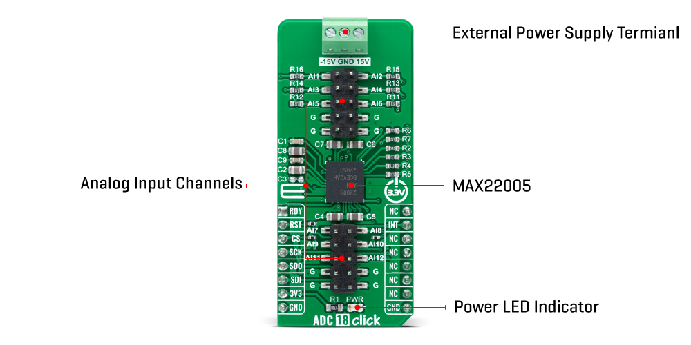
ADC 18 Click is a compact add-on board that contains a high-performance data converter. This board features the MAX22005, an SPI-configurable twelve-channel 24-bit analog-to-digital converter (ADC) from Analog Devices. Input channels can be used as twelve single-ended, six differential, and up to eight multichannel configurable differential inputs. In total, the device supports up to 26 different configurations. The ADC is used with an integrated 5ppm/°C precision reference. Using high-voltage, zero-drift input amplifiers, standard industrial analog input voltage ranges are converted to the ADC input voltage range. This Click board™ offers high accuracy for the most demanding applications, from general-purpose remote data acquisition to industrial applications.
ADC 18 Click is supported by a mikroSDK compliant library, which includes functions that simplify software development. This Click board™ comes as a fully tested product, ready to be used on a system equipped with the mikroBUS™ socket.
HOW DOES IT WORK?
ADC 18 Click as its foundation uses the MAX22005, a high-performance twelve-channel analog-to-digital converter from Analog Devices. The MAX22005 comes with an integrated 24-bit delta-sigma ADC, input multiplexer, signal conditioning, and control logic block allowing ADC to communicate with MCU through a high-speed serial interface. An integrated delta-sigma ADC is shared between all channels with an integrated 5ppm/°C precision reference. Using high-voltage, zero-drift input amplifiers, standard industrial analog input voltage ranges are converted to the ADC input voltage range.

Input channels can be used as twelve single-ended, six differential, and up to eight multichannel configurable differential inputs. In total, the device supports up to 26 different configurations. The MAX22005 can also be configured as an analog-input current-mode device using an external precision resistor per channel or configurable analog-input using an external precision resistor and low-cost switch per channel. All input ports are robustly protected up to ±36V reverse polarity and ±2kV surge pulses without the need for TVS diodes and factory calibrated with a best-in-class system performance of less than 0.05% FSR Total-Unadjusted-Error (TUE) over temperature.
ADC 18 Click communicates with MCU through a standard SPI interface and operates at clock rates up to 30MHz, for all configurations and information management and acquiring conversion results. In addition, it also uses several mikroBUS™ pins. An active-low reset signal routed on the RST pin of the mikroBUS™ socket activates a hardware reset of the system, while the INT pin on the mikroBUS™ socket represents a standard interrupt feature providing a user with feedback information. It also has an additional data ready interrupt marked as RDY and routed on the AN pin of the mikroBUS™ socket, used to signal when a new ADC conversion result is available in the data register.
This Click board™ can be operated only with a 3.3V logic voltage level. It also has an analog inputs external power supply terminal where it is necessary to bring ±15V to accept ± 10V inputs, whose full-scale range is ± 12.5V. The board must perform appropriate logic voltage level conversion before using MCUs with different logic levels. However, the Click board™ comes equipped with a library containing functions and an example code that can be used, as a reference, for further development.
SPECIFICATIONS
| Type | ADC |
| Applications | Can be used for the most demanding applications, from general-purpose remote data acquisition to industrial applications |
| On-board modules | MAX22005 - twelve-channel analog-to-digital converter from Analog Devices |
| Key Features | Factory-calibrated configurable industrial-analog input, high accuracy, software configurability, 24-bit sigma-delta ADC, low power consumption, high-speed serial interface, high performance, and more |
| Interface | SPI |
| Compatibility | mikroBUS |
| Click board size | L (57.15 x 25.4 mm) |
| Input Voltage | 3.3V,External |
PINOUT DIAGRAM
This table shows how the pinout on ADC 18 Click corresponds to the pinout on the mikroBUS™ socket (the latter shown in the two middle columns).
ONBOARD SETTINGS AND INDICATORS
| Label | Name | Default | Description |
|---|---|---|---|
| LD1 | PWR | - | Power LED Indicator |
| J1-J2 | - | Populated | Analog Input Channel Headers |
ADC 18 CLICK ELECTRICAL SPECIFICATIONS
| Description | Min | Typ | Max | Unit |
|---|---|---|---|---|
| Supply Voltage | - | 3.3 | - | V |
| Input-Voltage Range | - | ±15 | - | V |
| Resolution | - | 24 | - | bits |
| Operating Temperature Range | -40 | +25 | +120 | °C |
Enter the code in the box below:


